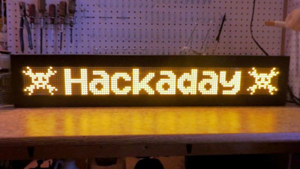
When his makerspace was gifted a pair of Luminator LED signs of the sort you might see on the front of a bus, [PWalsh] decided to pull one apart to see what made it tick. Along the way, he managed to reverse engineer its control protocol and replace its original control board with a WiFi-connected Raspberry Pi. Now they can use the LED signs to show whatever they want; no bus required.
As they were designed for automotive use, the signs were wired for 12 volts DC. So the first order of business was fitting it with an AC/DC converter so it could be plugged into the wall. After he measured the display’s current consumption, [PWalsh] estimated it’s maximum energy consumption and determined an old ATX computer power supply was more than up to the task.
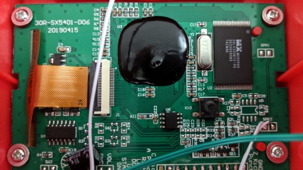
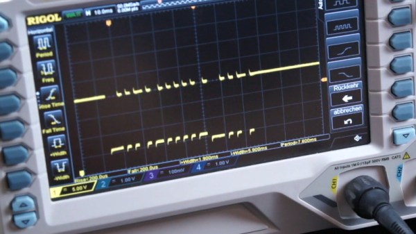
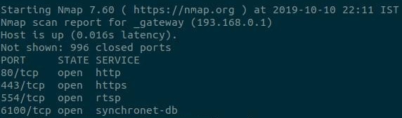
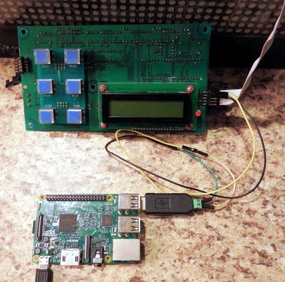 With the sign happily running battery-free, he could begin figuring out how to talk to it. Noticing a MAX485 RS-485 converter on the PCB, gave a pretty good idea of what language it was speaking, and with the aid of his trusty oscilloscope, he was able to suss out the baud rate. A cheap USB to RS-485 converter was then wired in between the sign and its control board so he could sniff the data passing over the line.
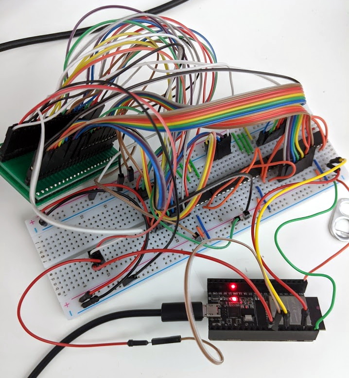
From there, the final piece of the puzzle was studying the captured data and figuring out the protocol. [PWalsh] was able to identify packet headers and ASCII characters, and pretty soon knew enough about how the sign communicated that he was able to remove the control board entirely and just push text and images to it right from the Pi. He’s even made his framework available for anyone else who might have a similar piece of bus-signage laying around.
Even if you’re not looking to add one of these signs to your lab, this project is a fantastic example of protocol reverse engineering with low-cost tools and simple techniques. We always love to see the process broken down step by step like this, and our hat’s off to [PWalsh] for delivering the goods in a big way.
This isn’t the first time we’ve seen these sort of LED signs get the “Internet of Things” treatment, and if you’re content with a somewhat scaled down version, you could always just build your own display rather than waiting on the local public transit vehicle to get parted out.