Fake Ram: Identifying A Counterfeit Chip

[Robert Baruch‏] had something strange on his hands. He had carefully decapped 74LS189 16×4 static RAM, only to find that it wasn’t a RAM at all. The silicon die inside the plastic package even had analog elements, which is not what one would expect to find in an SRAM. But what was it? A quick tweet brought in the cavalry, in the form of chip analysis expert [Ken Shirriff].

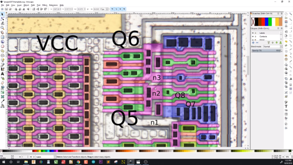
[Ken] immediately realized the part [Robert] had uncovered wasn’t a 74 series chip at all. The power and ground pins were in the wrong places. Even the transistors were small CMOS devices, where a 74 series part would use larger bipolar transistors. The most glaring difference between the mystery device and a real LS819 was the analog elements. The mystery chip had a resistor network, arranged as an R-2R ladder. This configuration is often used as a simple Digital to Analog Converter (DAC).

Further analysis of the part revealed that the DAC was driven by a mask ROM that was itself indexed using a linear feedback shift register. [Ken] used all this information to plot out the analog signal the chip would generate. It turned out to be a rather sorry looking sine wave.

The mystery part didn’t look like any function generator or audio chip of the era. [Ken] had to think about what sort of commodity part would use lookup tables to generate an audio waveform. The answer was as close as his telephone — a DTMF “touch tone” generator, specifically a knockoff of a Mostek MK5085.

Most investigators would have stopped there. Not [Ken] though. He delved into the construction and function of the DTMF generator. You can find the full analysis on his site. This isn’t [Ken’s] first rodeo with decapped chips. He’s previously examined the Intel 8008 and presented a talk on silicon reverse engineering at the 2016 Hackaday Superconference. [Robert] has also shown us how to pop the top of classic ceramic integrated circuits.


Reverse Engineering A BLE Service To Control A Light Bulb

So, you buy an Internet of Things light bulb, it’s a fun toy that allows you to bathe your environment in pretty colours at the touch of an app, but eventually you want more. You start to wonder how you might do more with it, and begin to investigate its inner workings. Then to your horror you discover that far from having bought a device with a convenient API for you to use, it has an impenetrable closed protocol that defies easy access.

This was the problem facing [Ayan Pahwa] when he bought a Syska Smartlight Rainbow LED bulb, and discovered that its Bluetooth Low Energy  interface used a closed protocol. But instead of giving up, he proceeded to reverse engineer the communication between bulb and app, and his write-up makes for an interesting read that provides a basic primer on some of BLE’s workings for the uninitiated.

BLE allows a device manufacturer to define their own device service specific to their functionality alongside standard ones for common device types. Using a handy Android app from Nordic Semiconductor he was able to identify the services defined for the light bulb, but sadly they lacked any human-readable information to help him as to their purpose. He thus had to sniff BLE packets directly, and lacking dedicated hardware for this task he relied on a developer feature built into Android versions since KitKat, allowing packets to be captured and logged. By analysing the resulting packet files he was able to identify the Texas Instruments chip inside the bulb, and to deduce the sequences required to control its colours. Then he was able to use the Bluez utilities to talk directly to it, and as if by magic, his colours appeared! Take a look at the video we’ve placed below the break.

Many of us may never need to reverse engineer a BLE device. But if we are BLE novices, after reading [Ayan]’s piece we will at least have some idea of its inner workings. And that can only be a positive thing.

Continue reading “Reverse Engineering A BLE Service To Control A Light Bulb”

Michael Ossmann Pulls DSSS Out Of Nowhere

[Michael Ossmann] spoke on Friday to a packed house in the wireless hacking village at DEF CON 25. There’s still a day and a half of talks remaining but it will be hard for anything to unseat his Reverse Engineering Direct Sequence Spread Spectrum (DSSS) talk as my favorite of the con.

DSSS is a technique used to transmit reliable data where low signal strength and high noise are likely. It’s used in GPS communications where the signal received from a satellite is often far too small for you to detect visually on a waterfall display. Yet we know that data is being received and decoded by every cell phone on the planet. It is also used for WiFi management packets, ZigBee, and found in proprietary systems especially any dealing with satellite communications.

[Michael] really pulled a rabbit out of a hat with his demos which detected the DSSS signal parameters in what appeared to be nothing but noise. You can see below the signal with and without noise; the latter is completely indiscernible as a signal at all to the eye, but can be detected using his techniques.

Detecting DSSS with Simple Math

[Michael] mentioned simple math tricks, and he wasn’t kidding. It’s easy to assume that someone as experienced in RF as he would have a different definition of ‘simple’ than we would. But truly, he’s using multiplication and subtraction to do an awful lot.

DSSS transmits binary values as a set called a chip. The chip for digital 1 might be 11100010010 with the digital 0 being the inverse of that. You can see this in the slide at the top of this article. Normal DSSS decoding compares the signal to expected values, using a correlation algorithm that multiplies the two and gives a score. If the score is high enough, 11 in this example, then a bit has been detected.

To reverse engineer this it is necessary to center on the correct frequency and then detect the chip encoding. GNU radio is the tool of choice for processing a DSSS capture from a SPOT Connect module designed to push simple messages to a satellite communication network. The first math trick is to multiply the signal by itself and then look at spectrum analysis to see if there is a noticeable spike indicating the center of the frequency. This can then be adjusted with an offset and smaller spikes on either side will be observed.

When visualized in a constellation view you begin to observe a center and two opposite clusters. The next math trick is to square the signal (multiply it by itself) and it will join those opposite clusters onto one side. What this accomplishes is a strong periodic component (the cycle from the center to the cluster and back again) which reveals the chip rate.

Detecting symbols within the chip is another math trick. Subtract each successive value in the signal from the last and you will mostly end up with zero (high signal minus high signal is zero, etc). But every time the signal spikes you’re looking at a transition point and the visualization begins to look like logic traced out on an oscilloscope. This technique can deal with small amounts of noise but becomes more robust with a bit of filtering.

This sort of exploration of the signal is both fun and interesting. But if you want to actually get some work done you need a tool. [Michael] built his own in the form of a python script that cobbles up a .cfile and spits out the frequency offset, chip rate, chip sequence length, and decoded chip sequence.

Running his sample file through with increasing levels of noise added, the script was rock solid on detecting the parameters of the signal. Interestingly, it is even measuring the 3 parts per million difference between the transmitter and receiver clocks in the detected chip rate value. What isn’t rock solid is the actual bit information, which begins to degrade as the noise is increased. But just establishing the parameters of the protocol being used is the biggest part of the battle and this is a dependable solution for doing that quickly and automatically.

You can give the script a try. It is part of [Michael’s] Clock Recovery repo. This talk was recorded and you should add it to your reminder list for after the con when talks begin to be published. To hold you over until then, we suggest you take a look at his RF Design workshop from the 2015 Hackaday Superconference.

RoGeorge Attacks A Pulse Meter

The “Crivit Sports” is an inexpensive chest-strap monitor that displays your current pulse rate on a dedicated wristwatch. This would be much more useful, and presumably more expensive, if it had a logging option, or any way to export your pulse data to a more capable device. So [RoGeorge] got to work. Each post of the (so-far) three-part series is worth a read, not the least because of the cool techniques used.

In part one, [RoGeorge] starts out by intercepting the signals. His RF sniffer? An oscilloscope probe shorted out in a loop around the heart monitor. Being able to read the signals, it was time to decode them. Doing pushups and decoding on-off keyed RF signals sounds like the ideal hacker training regimen, but instead [RoGeorge] used a signal generator, clipped to the chest monitor, to generate nice steady “heartbeats” and then read the codes off the scope without breaking a sweat.

With the encoding in hand, and some help from the Internet, he tested out his hypothesis in part two. Using an Arduino to generate the pulses logged in part one, he pulsed a coil and managed to get the heart rates displayed on the watch.

Which brings us to part three. What if there were other secrets to be discovered? Brute-forcing every possible RF signal and looking at the watch to see the result would be useful, but doing so for 8,192 possible codes would drive anyone insane. So [RoGeorge] taught himself OpenCV in Python and pointed a webcam at the watch. He wrote a routine that detected the heart icon blinking, a sign that the watch received a valid code, and then transmitted all possible codes to see which ones were valid. Besides discovering a few redundant codes, he didn’t learn much new from this exercise, but it’s a great technique.

We’re not sure what’s left to do on the Crivit. [RoGeorge] has already figured out the heart-rate data protocol, and could easily make his own logger. We are sure that we liked his thorough and automated approach to testing it all, from signal-generator-as-heartbeat to OpenCV as feedback in a brute-force routine. We can’t wait to see what’s up next.

Completely Owning The Dreamcast Add-on You Never Had

If you’ve got a SEGA Dreamcast kicking around in a closet somewhere, and you still have the underutilized add-on Visual Memory Unit (VMU), you’re in for a treat today. If not, but you enjoy incredibly detailed hacks into the depths of slightly aged silicon, you’ll be even more excited. Because [Dmitry Grinberg] has a VMU hack that will awe you with its completeness. With all the bits in place, the hacking tally is a new MAME emulator, an IDA plugin, a never-before ROM dump, and an emulator for an ARM chip that doesn’t exist, running Flappy Bird. All in a month’s work!

The VMU was a Dreamcast add-on that primarily stored game data in its flash memory, but it also had a small LCD display, a D-pad, and inter-VMU communications functions. It also had room for a standalone game which could interact with the main Dreamcast games in limited ways. [Dmitry] wanted to see what else he could do with it. Basically everything.

We can’t do this hack justice in a short write-up, but the outline is that he starts out with the datasheet for the VMU’s CPU, and goes looking for interesting instructions. Then he started reverse engineering the ROM that comes with the SDK, which was only trivially obfuscated. Along the way, he wrote his own IDA plugin for the chip. Discovery of two ROP gadgets allowed him to dump the ROM to flash, where it could be easily read out. Those of you in the VMU community will appreciate the first-ever ROM dump.

On to doing something useful with the device! [Dmitry]’s definition of useful is to have it emulate a modern CPU so that it’s a lot easier to program for. Of course, nobody writes an emulator for modern hardware directly on obsolete hardware — you emulate the obsolete hardware on your laptop to get a debug environment first. So [Dmitry] ported the emulator for the VMU’s CPU that he found in MAME from C++ to C (for reasons that we understand) and customized it for the VMU’s hardware.

Within the emulated VMU, [Dmitry] then wrote the ARM Cortex emulator that it would soon run. But what ARM Cortex to emulate? The Cortex-M0 would have been good enough, but it lacked some instructions that [Dmitry] liked, so he ended up writing an emulator of the not-available-in-silicon Cortex-M23, which had the features he wanted. Load up the Cortex emulator in the VMU, and you can write games for it in C. [Dmitry] provides two demos, naturally: a Mandlebrot set grapher, and Flappy Bird.

Amazed? Yeah, we were as well. But then this is the same guy emulated an ARM chip on the AVR architecture, just to run Linux on an ATMega1284p.

Getting Data Off Proprietary Glucometers Gets A Little Easier

Glucometers (which measure glucose levels in blood) are medical devices familiar to diabetics, and notorious for being proprietary. Gentoo Linux developer [Flameeyes] has some good news about his open source tool to read and export data from a growing variety of glucometers. For [Flameeyes], the process started four years ago when he needed to send his glucometer readings to his doctor and ended up writing his own tool. Previously it was for Linux only, but now has Windows support.

Glucometers use a variety of different data interfaces, and even similar glucometers from the same manufacturer can use different protocols. Getting the data is one thing, but more is needed. [Flameeyes] admits that the tool is still crude in many ways, lacking useful features such as HTML output. Visualization and analysis are missing as well. If you’re interested in seeing if you can help, head over to the GitHub repository for glucomerutils. Also needed are details on protocols used by different devices; [Flameeyes] has only been able to reverse-engineer the protocols of meters he owns.

Speaking of glucometers, there is a project for a Universal Glucometer which aims to be able to use test strips from any manufacturer without needing to purchase a different meter.

Thanks for the tip, [Stuart]!

Reverse Engineering The Monoprice Printer

When the Monoprice MP Select Mini 3D printer was released last year, it was a game changer. This was a printer for $200, yes, but it also held a not-so-obvious secret: a 3D printer controller board no one had ever seen before powered by a 32-bit ARM microcontroller with an ESP8266 handling the UI. This is a game-changing set of electronics in the world of 3D printing, and now, finally, someone is reverse engineering it.

[Robin] began the reverse engineering by attaching the lead of an oscilloscope to the serial line between the main controller and display controller. The baud rate is weird (500 kHz), but apart from that, the commands readily appear in human-parsable text. There is a web server built into the MP Mini printer, and after inspecting the web page that’s served up from this printer, [Robin] found it was possible to send G-code directly from the controller board, get a list of files on the SD card, and do everything you would want to do with a 3D printer.

After deconstructing the circuit on the display board, [Robin] found exactly what you would expect from such a simple board: an SPI display driven by an ESP, and a big flash chip sitting off to the side. [Robin] found the the model of the display, and quickly built a project on Platform.io to draw text to the LCD. This isn’t the end of the project – there’s still a lot that must be done before this printer is squirting out parts with custom firmware.

While this isn’t a hack of the driver board inside the MP Mini, that’s not really a problem. The motor driver board in this printer doesn’t really need any changes, and was already ahead of its time when this printer was released last year. As with most things, the UI is the weak point, and upgrading the firmware and built-in web server for this printer is the best way forward.

[Robin] put together a truly phenomenal video of how he reverse engineered this display controller. You can check that out below.

Continue reading “Reverse Engineering The Monoprice Printer”