Reverse Engineering The SEGA Mega Drive

With the widespread adoption of emulators, almost anyone can start playing video games from bygone eras. Some systems are even capable of supporting homebrew games, with several having active communities that are still creating new games even decades later. This ease of programming for non-PC platforms wasn’t always so easy, though. If you wanted to develop games on a now-antique console when it was still relatively new, you had to jump through a lot of hoops. [Tore] shows us how it would have been done with his Sega Mega Drive development kit that he built from scratch.

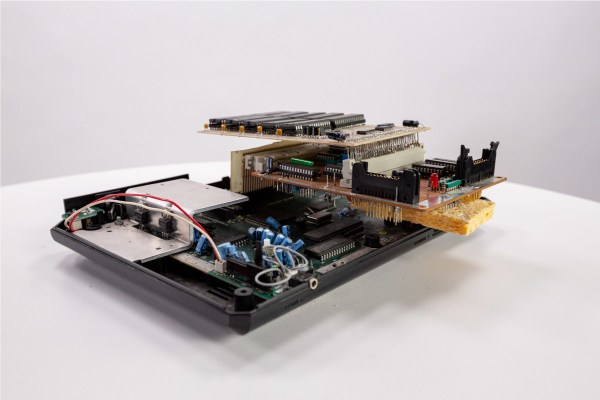
While [Tore] had an Atari ST, he wanted to do something a little more cutting edge and at the time there was nothing better than the Mega Drive (or the Genesis as it was known in North America). It had a number of features that lent the platform to development, namely the Motorola 68000 chip that was very common for the time and as a result had plenty of documentation available. He still needed to do quite a bit of reverse engineering of the system to get a proper dev board running, though, starting with figuring out how the cartridge system worked. He was able to build a memory bank that functioned as a re-writable game cartridge.

With the hard parts out of the way [Tore] set about building the glue logic, the startup firmware which interfaced with his Atari ST, and then of course wiring it all together. He was eventually able to get far enough along to send programs to the Mega Drive that would allow him to control sprites on a screen with the controller, but unfortunately he was interrupted before he could develop any complete games. The amount of research and work to get this far is incredible, though, and there may be some helpful nuggets for anyone in the homebrew Mega Drive community today. If you don’t want to get this deep into the Mega Drive hardware, though, you can build a cartridge that allows for development on native Sega hardware instead.

ASCII Schematic Diagrams

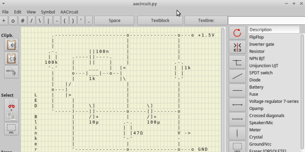
We wondered recently about those crude ASCII schematics you see in some documentation — are there any dedicated schematic-focused tools to draw them, or are they just hand-crafted using various ASCII-art drawing tools? To our surprise, there is such a tool. It is called AACircuit and was developed by [Andreas Weber]. It has a history going back to 2001 when it was first introduced as ASCIIPaint. Be forewarned, however, the quality of the code may be questionable. According to the notes on [Andy]’s GitHub repository:

WARNING: a lot of spaghetti code ahead

This code was created in 2001-2004 when I taught Borland Delphi 3 to myself. It contains many, many global variables, unstructured and undocumented procedural code and bad variable names.

If you don’t want to wrestle with old and sketchy object-oriented Pascal code, you’re in luck. [Chaos Ordered] has made a Pythonized version which you can get from his GitHub repository. We tried it out and got it working on Ubuntu in short order (after wrestling with a pycairo dependencies). This might not be everyone’s cup of tea, but it has some uses now and then. While we wouldn’t want to document a computer motherboard with ASCII schematics, it’s great for a quick-and-dirty circuit diagrams.

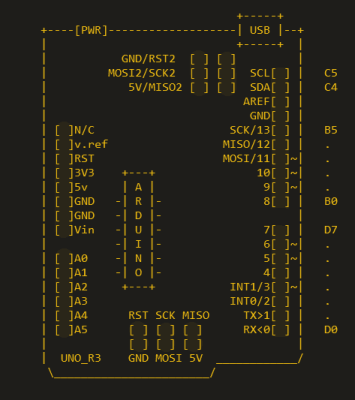
Not exactly schematics, but [Duckman] has some Arduino pinout diagrams he made using ASCII-art. These could be useful when pasted into source code as comments, documenting the pinouts for your project.

Do you recommend any tools for making ASCII schematics, or this just a waste of time?

DIY 8-Bit Computer Knows All The Tricks

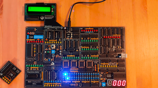
Some projects are a rite of passage within their respected fields. For computer science, building one’s own computer from scratch is certainly among those projects. Of course, we’re not talking about buying components online and snapping together a modern x86 machine. We mean building something closer to a fully-programmable 8-bit computer from the ground up, like this one from [Federico] based on 74LS logic chips.

The computer was designed and built from scratch which is impressive enough, but [Federico] completed this project in about a month as well. It can be programmed manually through DIP switches or via a USB connection to another computer, and also includes an adjustable clock which can perform steps anywhere from 1 Hz to 32 kHz. Complete with a 1024 byte memory, a capable ALU, four seven-segment LEDs and (in the second version of the computer) a 2×16 LCD disply, this 8-bit computer has it all.

Not only is this a capable machine designed by someone who clearly knows his way around a logic chip, but [Federico] has also made the code and schematics available on his GitHub page. It’s worth a read even without building your own, but if you want to go that route without printing an enormous PCB you can always follow the breadboard route.

Thanks to [killergeek] for the tip!

Continue reading “DIY 8-Bit Computer Knows All The Tricks”

You’ll Flip For This 7404 IC Motherboard Fix

We often lament that the days of repairable electronics are long gone. It used to be you’d get schematics for a piece of gear, and you could just as easily crack it open and fix something as the local repairman — assuming you had the knowledge and tools. But today, everything is built to be thrown away when something goes wrong, and you might as well check at the end of a rainbow if you’re searching for a circuit diagram for a new piece of consumer electronics.

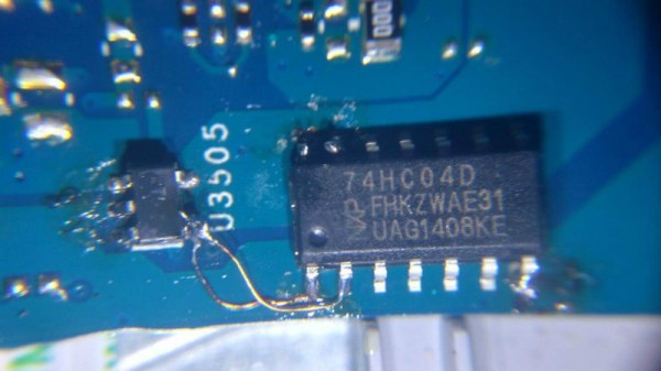
But [Robson] writes in with an interesting story that gives us hope that the “old ways” aren’t gone completely, though they’ve certainly changed for the 21st century. After blowing out his laptop’s USB ports when he connected a suspect circuit, he was desperate for a fix that would fit his student budget (in other words, nearly zero). Only problem was that he had no experience fixing computers. Oh, and it takes months for his online purchases to reach him in Brazil. Off to a rocky start.

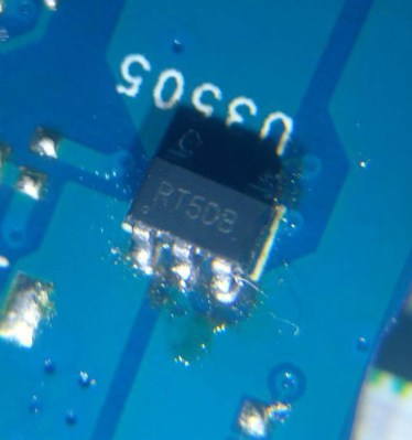
His first bit of luck came with the discovery he could purchase schematics for his laptop online. Now, we can’t vouch for the site he used (it sure isn’t direct from Dell), but for under $5 USD [Robson] apparently got complete and accurate schematics that let him figure out what part was blown on the board without even having to open up the computer. All he had to do was order a replacement IC (SY6288DAAC), and solder it on. It took two months for the parts to arrive, and had to do it with an iron instead of a hot air station, but in the end, he got the part installed.

Continue reading “You’ll Flip For This 7404 IC Motherboard Fix”

KiCad Video Series: From Concept To Manufacture

Many of our readers took the habit of using Eagle to design their PCBs. Even if you’ll find plenty of support for this software as well as a lot of parts libraries, the software comes with limitations. The useable board area is limited to 4×3.2 inches, only two signal layers can be used and more importantly the schematics editor can only create one sheet. On the other side, some of you may already know KiCad, a free open source and unrestricted schematics and layout software. [Chris] just tipped us of a video series he made, showing people how to design and build their very first PCB using this software. It’s a simple 555 circuit, but goes through all the steps necessary to design a PCB that costs only $5 through OSHpark… and will blink by the end. All the videos are also embedded after the break.

Continue reading “KiCad Video Series: From Concept To Manufacture”

Visualizing PCB Revisions Using A Gerber Viewer

gerber_schematic_highlighting

We all know that Eagle has its share of shortcomings. Instructables user [westfw] was particularly annoyed by the fact that while Eagle keeps copies of up to 10 revisions of your board, it cannot open those files without resorting to manually renaming each one. Even more frustrating to him is the fact that you can’t use Eagle to view two files simultaneously in order to compare layouts. This made hunting down changes quite tedious, so he started looking for a better way to do things.

While using his favorite open-source gerber viewer gerbv, he noticed that the application let him load multiple copies of the same layer, XORing the PCBs’ colors together. Realizing that with some clever color selection, he could use gerbv to automatically highlight layout differences, he set off to automate the process.

The resulting script works on any flavor of *nix, and should play nice in Windows under cygwin as well. The script reads through Eagle backup files, renaming them and tweaking the colors so that when XORed, they show up as bright red areas in gerbv. It’s a simple yet handy tool to have on hand if you happen to do a lot of PCB design.

CircuitBee Makes Sharing Schematics And Circuit Diagrams Easy

circuit_bee_schematic_hosting

When looking for things to write about, there is nothing we like to see more than well-documented schematics and code available for download. In the case of schematics, we realize that they can be a bit of a pain to publish. Many times we see them in the form of blurry JPEGs or humungous PDF files, neither of which are incredibly convenient to use. The folks over at CircuitBee thought the same thing, and have been working diligently to make it easier for everyone to share their awesome ideas with the world.

Their free service requires registration, and not much else. Once you’re in, you are free to upload your Eagle or KiCAD circuit diagrams, which are then run through CircuitBee’s servers. They convert your drawings into embeddable objects which allow others to view your project without a lot of fuss. Their embeddable schematic window can be rendered in full screen mode, and gives users the ability to zoom in on any portion of the drawing to see the circuit’s finer details.

[Ben Delarre] from CircuitBee says that the product is in the alpha stages right now, so there are plenty of features and useful tools coming in the near future. If you like to build and share, it’s definitely something worth checking out!

[via Make]

[Thanks, Sanchoooo]