Low Tech High Safety And The NYC Subway System

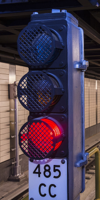
The year is 1894. You are designing a train system for a large city. Your boss informs you that the mayor’s office wants assurances that trains can’t have wrecks. The system will start small, but it is going to get big and complex over time with tracks crossing and switching. Remember, it is 1894, so computing and wireless tech are barely science fiction at this point. The answer — at least for the New York City subway system — is a clever system of signals and interlocks that make great use of the technology of the day. Bernard S. Greenberg does a great job of describing the system in great detail.

The subway began operation in 1904, well over 30 years since the above-ground trains began running. A clever system of signals and the tracks themselves worked together with some mechanical devices to make the subway very safe. Even if you tried to run two trains together, the safety systems would prevent it.

On the face of it, the system is very simple. There are lights that show red, yellow, and green. If you drive, you know what these mean. But what’s really interesting is the scheme used at the time to make them light.

Continue reading “Low Tech High Safety And The NYC Subway System”

Cut Through The Noise, See Tiny Signals

An oscilloscope is a handy tool for measuring signals of all kinds, but it’s especially useful if you want to measure something with a periodic component. Modern oscilloscopes have all kinds of features built-in that allow you sample a wide range of signals in the hundreds of megahertz, and make finding and measuring your signal pretty easy, provided you know which buttons to push. There are some advanced oscilloscope methods that go beyond the built-in features of even the best oscilloscopes, and [AM] has a tutorial on one of them.

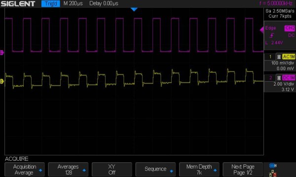
The method used here is called phase-senstitive detection, and allows tiny signals to be found within noise, even if the magnitude of the noise is hundreds of times greater than the signal itself. Normally this wouldn’t be possible, but by shifting the signal out of the DC range and giving it some frequency content, and then using a second channel on the oscilloscope to measure the frequency content of the source and triggering the oscilloscope on the second channel, the phase of the measured signal can be sifted out of the noise and shown clearly on the screen.

In [AM]’s example, he is measuring the intensity of a laser using a photodiode with a crude amplifier, but even with the amplifier it’s hard to see the signal in the noise. By adding a PWM-like signal to the power source of the laser and then syncing it up with the incoming signal from the photodiode, he can tease out the information he needs. It’s eally a fascinating concept, and if you fancy yourself a whiz with an oscilloscope this is really a tool you should have in your back pocket.  If you’re new to this equipment, we do have a primer on some oscilloscope basics, too.

Continue reading “Cut Through The Noise, See Tiny Signals”

Old Time Traffic Signal Revived With A Raspberry Pi Controller

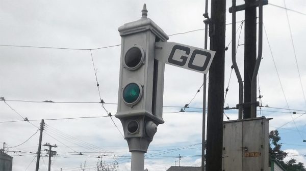
Anyone with even a passing familiarity with the classic animated shorts of the 1940s will recognize the traffic signal in the image above. Yes, such things actually existed in the real world, not just in the Looney world of [Bugs Bunny] et al. As sturdy as such devices were, they don’t last forever, though, which is why a restoration of this classic Acme traffic signal was necessary for a California museum. Yes, that Acme.

When you see a traffic signal from the early days of the automotive age like this one, it becomes quickly apparent how good the modern equivalent has become. Back in the day, with a mix of lights distributed all over the body of the signal, arms that extend out, and bells that ring when the state changes, it’s easy to see how things could get out of hand at an intersection. That complexity made the restoration project by [am1034481] and colleagues at the Southern California Traffic Museum all the more difficult. Each signal has three lights, a motor for the flag, and an annunciator bell, each requiring a relay. What’s more, the motor needs to run in both directions, so a reversing relay is needed, and the arm has a mechanism to keep it in position when motor power is removed, which needs yet another relay. With two signals, everything was doubled, so the new controller used a 16-channel relay board and a Raspberry Pi to run through various demos. To keep induced currents from wreaking havoc, zero-crossing solid state relays were used on the big AC motors and coils in the signal. It looks like a lot of work, but the end results are worth it.

Looking for more information on traffic signal controls? We talked about that a while back.

Turning Television Into A Simple Tapestry

Teleknitting, the brainchild of Moscow artist [vtol], is an interesting project. On one hand, it doesn’t knit anything that is useful in a traditional sense, but on the other, it attempts the complex task of deconstructing broadcasted media into a simpler form of information transmission.

Teleknitting’s three main components are the processing and display block — made up of the antenna, Android tablet, and speaker — the dyeing machine with its ink, sponges, actuators, and Arduino Uno, and the rotating platform for the sacrificial object. A program running on the tablet analyzes the received signal and — as displayed on its screen — gradually halves the number of pixels in the image until there is only one left with a basic representation of the picture’s colour. From there, thread passes over five sponges which dye it the appropriate colour, with an armature that responds to the broadcast’s volume directing where the thread will bind the object.

Continue reading “Turning Television Into A Simple Tapestry”

Wifi Antenna

Simple Directional WiFi Antenna

Back in 2007, [Stathack] rented an apartment in Thailand. This particular apartment didn’t include any Internet access. It turned out that getting a good connection would cost upwards of $100 per month, and also required a Thai identification card. Not wanting to be locked into a 12-month contract, [Stathack] decided to build himself a directional WiFi antenna to get free WiFi from a shop down the street.

The three main components of this build are a USB WiFi dongle, a baby bottle, and a parabolic Asian mesh wire spoon. The spoon is used as a reflector. The parabolic shape means that it will reflect radio signals to a specific focal point. The goal is to get the USB dongle as close to the focal point as possible. [Stathack] did a little bit of math and used a Cartesian equation to figure out the optimal location.

Once the location was determined, [Stathack] cut a hole in the mesh just big enough for the nipple of the small baby bottle. The USB dongle is housed inside of the bottle for weatherproofing. A hole is cut in the nipple for a USB cable. Everything is held together with electrical tape as needed.

[Stathack] leaves this antenna on his balcony aiming down the street. He was glad to find that he is easily able to pick up the WiFi signal from the shop down the street. He was also surprised to see that he can pick up signals from a high-rise building over 1km away. Not bad for an antenna made from a spoon and a baby bottle; plus it looks less threatening than some of the cantenna builds we’ve seen.

DIY Optoisolator

MacGyvered Optoisolator Is A Great Introduction

Sometimes the best way to learn about a technology is to just build something yourself. That’s what [Dan] did with his DIY optoisolator. The purpose of an optoisolator is to allow two electrical systems to communicate with each other without being electrically connected. Many times this is done to prevent noise from one circuit from bleeding over into another.

[Dan] built his incredibly simple optoisolator using just a toilet paper tube, some aluminum foil, an LED, and a photo cell. The electrical components are mounted inside of the tube and the ends of the tube are sealed with foil. That’s all there is to it. To test the circuit, he configured an Arduino to send PWM signals to the LED inside the tube at various pulse widths. He then measured the resistance on the other side and graphed the resulting data. The result is a curve that shows the LED affects the sensor pretty drastically at first, but then gets less and less effective as the frequency of the signal increases.

[Dan] then had some more fun with his project by testing it on a simple temperature controller circuit. An Arduino reads a temperature sensor and if the temperature rises above a certain value, it turns on a fan to cool the sensor off again. [Dan] first graphed the sensor data with no fan hooked up. He only used ambient air to cool things down. The resulting graph is a pretty smooth curve. Next he hooked the fan up and tried again. This time the graph went all kinds of crazy. Every time the fan turned on, it created a bunch of electrical noise that prevented the Arduino from getting an accurate analog reading of the temperature sensor.

The third test was to remove the motor circuit and move it to its own bread board. The only thing connecting the Arduino circuit to the fan was a wire for the PWM signal and also a common ground. This smoothed out the graph but it was still a bit… lumpy. The final test was to isolate the fan circuit from the temperature sensor and see if it helped the situation. [Dan] hooked up his optoisolator and tried again. This time the graph was nice and smooth, just like the original graph.

While this technology is certainly not new or exciting, it’s always great to see someone learning by doing. What’s more is [Dan] has made all of his schematics and code readily available so others can try the same experiment and learn it for themselves.

Retrotechtacular: Upgrading Train Signaling Before The Information Age

retrotechtacular-british-railway-signaling

What’s surprising about the subject of this week’s Retrotechtacular is that the subject is not from that long ago. But looking at the way in which the work was done makes it feel so far in the past. In 1974 the British Railways Board set out to modernize and interconnect the signaling system. What you see above is one of hundreds of old signal control houses slated to be replaced by an interconnected system.

These days we take this sort of thing for granted. But from the start of the project it’s clear how the technology available at the time limited the efficiency of the development process. We’re not talking about all of the electro-mechanical parts shown during the manufacturing part of the video. Nope, right off the bat the volumes of large-format paper schematics and logic diagrams seem daunting. Rooms full of engineers with stacks of bound planning documents feel alien to us since these days even having to print out a boarding pass seems antiquated.

With fantastic half-hour videos like this one available who needs television? We’d recommend adding this to your watch list so you can properly enjoy it. They show off everything; manufacturing the cables, stringing them between the signal towers, assembling the control panels, testing, and much more.

Continue reading “Retrotechtacular: Upgrading Train Signaling Before The Information Age”