[Ben Eater]’s Breadboarding Tips

A solderless breadboard is a place where ideas go to become real for the first time. Usually, this is a somewhat messy affair, with random jumpers flying all about the place, connecting components that can be quickly swapped to zero in on the right values, or to quickly change the circuit topology. Breadboards aren’t the place to make circuit artwork.
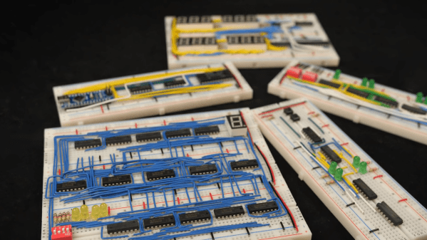
That is, however, not always the case, and we’ve seen more than a few examples from [Ben Eater] on breadboarding that approaches the circuit sculpture level of craftsmanship. And like any good craftsman, [Ben] has shared some of his breadboarding tips and tricks in a new video. Starting with a simple 555 blinkenlight project that’s wired up in the traditional anything-goes fashion, [Ben] walks us through his process for making a more presentation-worthy version.

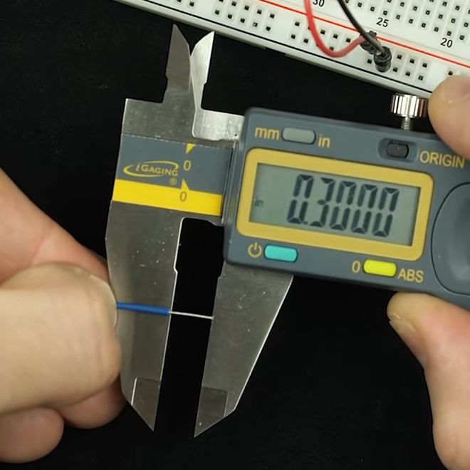
His tools are high-quality but simple, with the wire strippers being the most crucial to good results. Surprisingly, [Ben] relies most heavily on the simple “scissors-style” strippers for their versatility, rather than the complicated semi-automatic tools. We found that to be the biggest take-home from the video, as well as the results of practice. [Ben] has done tons of this type of breadboarding before, which means when he “eyeballs” stripping 0.3 inches of insulation, he can do it down to a ten-thousandth precision.

Granted, there’s not much new here, but watching this video is a little like watching [Bob Ross] paint — relaxing and strangely compelling at the same time. You can get more of the same with pretty much any of his videos that we’ve covered, like this 6502 breadboard computer build. We’ve also seen [Eater]-inspired builds that are pretty impressive, like this full-8-bit breadboard computer.

Continue reading “[Ben Eater]’s Breadboarding Tips”

Fail Of The Week: Z-Tape Is No Substitute For Solder

Here at Hackaday, we see all kinds of mechanical construction methods. Some are impressively solid and permanent, while others are obviously temporary in nature. The latter group is dominated by adhesives – sticky stuff like cyanoacrylate glue, Kapton tape, and the ever-popular hot glue. They’ve all got their uses in assembling enclosures or fixing components together mechanically, but surely they have no place in making solid electrical connections, right?

Maybe, maybe not. As [Tom Verbeure] relates, so-called Z-tape just might be an adhesive that can stand in for solder under certain circumstances. Trouble is, he couldn’t find the right conditions to make the tape work. Z-tape, more properly called “Electrically Conductive Adhesive Transfer Tape 9703”,  derives its nickname from the fact that it’s electrically conductive, but only in the Z-axis. [Tom] learned about Z-tape in [Joe FitzPatrick]’s malicious hardware prototyping workshop at the 2019 Hackaday Superconference, and decided to put it to the test.

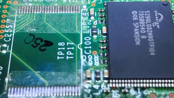
A card from a Cisco router served as a testbed thanks to an unpopulated chip footprint. The 0.5-mm pin spacing on the TSOP-48 chip was within spec for the Z-tape, but the area of each pin was 30 times smaller than the recommended minimum bonding area. While the chip was held down mechanically by the Z-tape, only five of the 48 pins were electrically connected to the pads. Emboldened by the partial success, [Tom] tried a 28-pin SOIC chip next. The larger pins and pads were still six times smaller than the minimum, and while more of the pins ended up connected by the tape, he was unable to make all 28 connections.

Reading the datasheet for the adhesive revealed that constant pressure from a clamp or clip might be necessary for reliable connections, which suggests that gluing down SMD chips is probably not the best application for the stuff. Still, we appreciate the effort, and the fine photomicrographs [Tom] made showing the particles within the Z-tape that make it work – at least in some applications.

Arcade1up Cabinet Mod Raspberry Pi 3

Arcade1up Cabinet Solderless Upgrade With A Side Of Raspberry Pi

Upon announcement of the Arcade1up replica arcade cabinets earlier this year, many laid in waiting for the day they could see a teardown. A four foot tall cab with an LCD outputting the proper 4:3 aspect ratio and the simple construction of IKEA furniture certainly seemed appealing. In theory, it wouldn’t take long to customize such a piece of hardware provided the internals lent themselves to that sort of thing. Now that the cabinets are on store shelves, [ETA Prime] made a tutorial video on his method for upgrading the Arcade1up cabinet with a Raspberry Pi calling the shots.

The entirety of the mod is solder-free and uses plenty of readily available parts from your favorite online reseller. The brains of the operation is a Raspberry Pi 3 Model B+ running Emulation Station. The Arcade1up Street Fighter 2 cabinet’s less than stellar audio receives an upgrade in a 2x20W car audio amp, while the middling joysticks are swapped out for some more robust Sanwa-clone ball tops.

Since there is no “select/coin” button natively, [ETA Prime] added some and in the process replaced them all with beefier LED-lit 30mm buttons. The replacement joysticks and buttons were all part of a kit, so they plug-in conveniently to a plug and play USB encoder. To adapt the 17″ LCD’s output over LVDS, [ETA Prime] elected to go with an LCD controller board that outputs DVI, VGA, or HDMI. Luckily the Arcade1up cabinet’s 12V power supply could be reused to power the LCD controller board and in the process bring down the overall cost of the upgrade.

While this Arcade1up cabinet mod won’t solve the whole “bats versus ball tops” argument, it does provide a template to build on. The tutorial video is below and the list of parts used can be found in the YouTube description.

Continue reading “Arcade1up Cabinet Solderless Upgrade With A Side Of Raspberry Pi”

Review: Hammer-Installed Solderless Raspberry Pi Pin Headers

A few days ago we reported on a new product for owners of the Raspberry Pi Zero, a set of solderless header pins that had a novel installation method involving a hammer. We were skeptical that they would provide a good contact, and preferred to stick with the tried-and-trusted soldered pins. It seems a lot of you agreed, and the comments section of the post became a little boisterous. Pimoroni, the originator of the product, came in for a lot of flak, with which to give them their due they engaged with good humor.

It’s obvious this was a controversial product, and maybe the Hackaday verdict had been a little summary based on the hammer aspect of the story. So to get further into what all the fuss had been about I ordered a Pi Zero and the solderless pin kit to try for ourselves.

Continue reading “Review: Hammer-Installed Solderless Raspberry Pi Pin Headers”

Heathkit’s Triumphant Return?

Heathkit, the storied purveyor of high-quality DIY electronics kits that inspired a generation of enthusiasts and launched the careers of many engineers, has returned from the dead. We think. At least it seems that way from this build log by [Spritle], an early adopter of the rebooted company’s first offering. But if [Spritle]’s experience is any indication, Heathkit has a long way to go to recreating its glory days. Continue reading “Heathkit’s Triumphant Return?”

Tube Prototyping Station

[Gio] enjoys using vacuum tubes in his projects. He designs the circuits using a CAD program but was finding that there is no substitute for actually building a prototype before heading to a final design. To make this process easier, he built his own tube prototyping station.

At the top of the board he’s got three different sizes of tube sockets with the pins from each wired as common. The nine pins from the sockets break out to a terminal strip where they can be interfaced with a solderless breadboard. For added versatility he’s included terminals to tap into some RCA jacks, as well as a 100 kOhm variable resistor. We’d bet this is not something that you can find ready-made, but it sure does look a whole lot better than a workbench full of components alligator-clipped together.