A Deep Drive Deep Dive Into A Twin-Rotor Motor

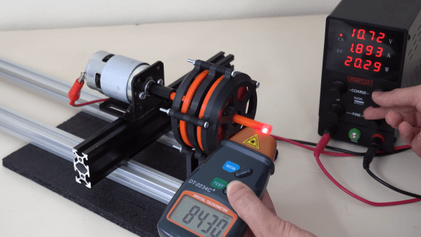
Compromise is key to keeping a team humming along. Say one person wants an inrunner electric motor, and the other prefers outrunner. What to do? Well, if you work at [Deep Drive], the compromise position is a dual-rotor setup that they claim can be up to 20% more efficient than standard designs. In a recent video, [Ziroth] provides a deep dive into Deep Drive’s Twin-Rotor Motor. 

This is specifically a radial flux permanent magnet motor, like most used in electric vehicles today — and don’t let talk of inrunners and outrunners fool you, that’s the size of motor we’re talking about here. This has been done before with axial flux motors, but it’s a new concept for team radial. As the names imply, the difference is the direction the magnetic field is orientated: axial flux motors have all the magnetism oriented along the axis, which leads to the short wide profile that inspired the nickname “pancake motors”. For various reasons, you’re more likely to see those on a PCB than in an electric car.

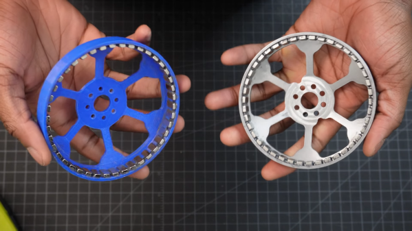
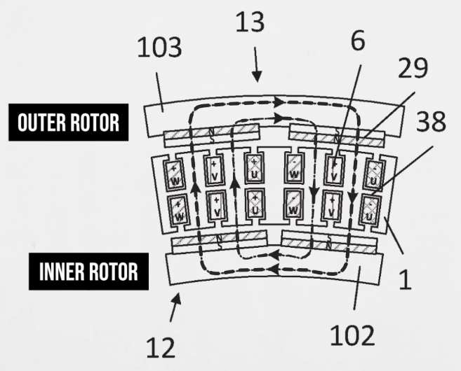
In a radial flux motor, the flux goes out the radius, so the coils and magnets are aligned around the shaft of the motor.  Usually, the coils are held by an iron armature that directs their magnetic flux inwards (or outwards) at the permanent magnets in the rotor, but not here. By deleting the metal armature from their design and putting magnets on both sides of the stator coil, Deep Drive claims to have built a motor that is lighter and provides more torque, while also being more energy-efficient.

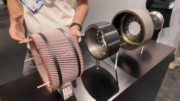
Of course you can’t use magnet wire if your coil is self-supporting, so instead they’re using hefty chunks of copper that could moonlight as busbars. In spite of needing magnets on both inner and outer rotors, the company says they require no more rare-earths than their competitors. We’re not sure if that is true for the copper content, though. To make the torque, those windings are beefy.

Still, its inspiring to see engineers continue to innovate in a space that many would have written off as fully-optimized. We look forward to seeing these motors in upcoming electric cars, but more than that, hope they sell a smaller unit for an air compressor so after going on a Deep Drive deep dive we can inflate our rubber raft with their twin rotor motor boater bloater. If it works as well as advertised, we might have to become twin-rotor motor boater bloater gloaters!

Continue reading “A Deep Drive Deep Dive Into A Twin-Rotor Motor”

Ender 3 Pro Gets A Second Job As A Stator Winder

Sometimes, you find yourself in need of a coil. You could sit around winding thousands of turns of copper wire yourself, but that would be remarkably tedious. Thus, instead, you might follow the example of [OJengineering] and choose to get a machine to do it for you.

This build first popped up on on Reddit, with [OJengineering] explaining that they had repurposed an Ender 3 Pro 3D printer to wind a stator for them. The reasoning was sound—a replacement stator for their motorcycle cost $1000 in their local area, so rewinding their own would be much cheaper. The idea was straightforward enough—the 3D printer was a capable motion control platform that really just needed to be retooled to drag wire around instead of squirting hot plastic. In a later update, they explained that they had created a Python program that spits out appropriate stator winding G-code from user-entered parameters. This G-code commands the 3D printer’s head to make rectangle winds around the stator core while moving up and down to appropriately distribute the wire. The device can be seen in action in a video on YouTube.

It’s a hacky build, but one that does nevertheless get the winding done. That’s the thing about 3D printers—they’re really just simple motion systems that can do whatever you tell them. You just need a way to generate the right G-code to do the job.

We’ve featured some other nifty coil winders before, too. Video after the break.

Continue reading “Ender 3 Pro Gets A Second Job As A Stator Winder”

3D Printed Air Raid Siren Sounds Just Like The Real Thing

Air raid sirens have an important job to do, and have been a critical piece of public safety infrastructure in times of geopolitical turmoil. They sound quite unlike anything else, by virtue of their mechanical method of generating an extremely loud sound output. They’re actually remarkably simple to build yourself, as [MarkMakies] demonstrates.

[Mark’s] build relies almost entirely on 3D printed components and ex-RC gear. The sound itself is generated by a rotor which spins inside a stator. Each is designed with special slots, such that as the rotor turns at speed, it creates spikes of air pressure that generate a loud wail. The rotor and stator are fitted inside a housing with a horn for output, which helps direct and amplify the sound further.

To spin the rotor, [Mark] used a powerful brushless motor controlled by a common hobby speed controller. The actual speed is determined by a potentiometer, which generates pulses to command the speed controller via a simple 555 circuit. By ramping the speed of the motor up and down, it’s possible to vary the pitch of the siren as is often done with real air raid sirens. This action could be entirely automated if so desired.

If you do decide to build such a siren, just be wary about how you use it. There’s no need to go around agitating the townsfolk absent an actual air raid. It’s worth noting that sirens of this type aren’t just used for air raids, either. They’re often used for tornado warnings, too, such as in Dallas, for example. But why not for music?

Continue reading “3D Printed Air Raid Siren Sounds Just Like The Real Thing”

Overcomplicating The Magnetic Compass For A Reason

Some inventions are so simple that it’s hard to improve them. The magnetic compass is a great example — a magnetized needle, a bit of cork, and a bowl of water are all you need to start navigating the globe. So why in the world would you want to over-complicate things with something like this Earth inductor compass? Just because it’s cool, of course.

Now, the thing with complication is that it’s often instructive. The simplicity of the magnetic compass masks the theory behind its operation to some degree and completely fails to deliver any quantitative data on the Earth’s magnetic field. [tsbrownie]’s gadget is built from a pair of electric motors, one intact and one stripped of its permanent magnet stators. The two are mounted on a 3D printed frame and coupled by a long shaft made of brass, to magnetically isolate them as much as possible. The motor is powered by a DC supply while a digital ammeter is attached to the terminals on the stator.

When the motor spins, the stator at the other end of the shaft cuts the Earth’s magnetic lines of force and generates a current, which is displayed on the ammeter. How much current is generated depends on how the assembly is oriented. In the video below, [tsbrownie] shows that the current nulls out when oriented along the east-west axis, and reaches a maximum along north-south. It’s not much current — about 35 microamps — but it’s enough to get a solid reading.

Is this a practical substitute for a magnetic compass? Perhaps not for most use cases, but a wind-powered version of this guided [Charles Lindbergh]’s Spirit of St. Louis across the Atlantic in 1927 with an error of only about 10 miles over the trip, so there’s that. Other aircraft compasses take different approaches to the problem of nulling out the magnetic field of the plane.

Continue reading “Overcomplicating The Magnetic Compass For A Reason”

Compact Cycloidal Drive Lives Inside This Custom Brushless Motor

With the popularity of robot dogs, many people have gotten on the bandwagon and tried building DIY versions. Most of them end up attaching a gearbox to an off-the-shelf brushless motor and call it a day. Not everyone goes that way, though, which is why this internal cycloidal drive actuator caught our eye.

Taking design cues from the MIT Mini Cheetah, [Aaed Musa] approached his actuator from the inside out, literally. His 3D printed cycloidal gearbox is designed to fit inside the stator of a BLDC motor. And not just any BLDC motor, but one built mostly from scratch using a hand-wound — and unwound, and wound again — stator along with a rotor that started as a printed part but was eventually machined from steel. Apart from its fixed ring, the cycloidal drive was mostly 3D printed, with everything fitting nicely inside the stator.

The video below shows the design and assembly process as well as testing of the finished drive. It seems to do really well with speed and positional accuracy, and it delivers a substantial amount of torque. Maybe a little too much, though; testing it with a heavy weight on the end of an arm got the stator coils hot enough to warp the printed parts within. But no matter; this was only a prototype after all. [Aaed] says improvements are in the works, including replacing all the plastic parts with metal ones.

Need a little background on cycloidal drives? They’re pretty cool.

Continue reading “Compact Cycloidal Drive Lives Inside This Custom Brushless Motor”

Magnetic Gearbox, Part 2: Axial Flux Improves Performance

The number of interesting and innovative mechanisms that 3D printing has enabled always fascinates us, and it’s always a treat when one of them shows up in our feeds. This axial flux magnetic gearbox is a great example of such a mechanism, and one that really makes you think about possible applications.

The principles of [Retsetman]’s gearbox are simple for anyone who has ever played with a couple of magnets to understand, since it relies on that powerful attractive and repulsive force you feel when magnets get close to each other. Unlike his previous radial flux gearbox, which used a pair of magnet-studded cylindrical rotors nested one inside the other, this design has a pair of disc-shaped printed rotors that face each other on aligned shafts. Each rotor has slots for sixteen neodymium magnets, which are glued into the slots in specific arrangements of polarity — every other magnet for the low-speed rotor, and groups of four on the high-speed rotor. Between the two rotors is a fixed flux modulator, a stator with ten ferromagnetic inserts screwed into it.

In operation, which the video below demonstrates nicely, the magnetic flux is coupled between the rotors by the steel inserts in the stator so that when one rotor moves, the other moves at a 4:1 (or 1:4) ratio in the opposite direction. [Retsetman] got the gearbox cranked up to about 8,500 RPM briefly, but found that extended operation at as little as 4,000 RPM invited disaster not due to eddy current heating of the inserts or magnets as one might expect, but from simple frictional heating of the rotor bearings.

Torque tests of the original gearbox were unimpressive, but [Retsetman]’s experiments with both laminated stator inserts and more powerful magnets really boosted the output — up to a 250% improvement! We’d also like to see what effect a Halbach array would have on performance, although we suspect that the proper ratios between the two rotors might be difficult to achieve.

Continue reading “Magnetic Gearbox, Part 2: Axial Flux Improves Performance”

Single Flex PCB Folds Into A Four-Wheel Rover, Complete With Motors

You’ve got to hand it to [Carl Bugeja] — he comes up with some of the most interesting electromechanical designs we’ve seen. His latest project is right up there, too: a single PCB that folds up into a four-wheel motorized rover.

The key to [Carl]’s design lies with his PCB brushless motors, which he has been refining since we first spotted them back in 2018. The idea is to use traces on the PCB for the stator coils to drive a 3D printed rotor containing tiny magnets. They work surprisingly well, even if they don’t generate a huge amount of torque. [Carl]’s flexible PCB design, which incorporates metal stiffeners, is a bit like an unfolded cardboard box, with two pairs of motor coils on each of the side panels. This leaves the other surfaces available for all the electronics, with includes a PIC, a driver chip, and a Hall sensor for each motor, an IMU and proximity sensor for navigation, and an ESP32 to run the show.

With machined aluminum rotors and TPU tires mounted to the folded-up chassis, it was off to the races, albeit slowly. The lack of torque from the motors and the light weight of the rover, along with some unwanted friction due to ill-fitting joints, added up to slow progress, especially on anything other than a dead flat surface. But with some tweaking, [Carl] was able to get the buggy working well enough to call this one a win. Check out the build and testing in the video below.

Knowing [Carl], this isn’t the last we’ll see of the foldable rover. After all, he stuck with his two-wheel PCB motor design and eventually got that running pretty well. We’ll be keeping an eye out for progress on this one.

Continue reading “Single Flex PCB Folds Into A Four-Wheel Rover, Complete With Motors”