Nothing beats a day on the lake in a little boat with an outboard motor putt-putting along behind you. It’s great fun, if perhaps a little noisy with all that putting going on. And maybe that oily sheen on the water in your wake is not so nice. it could be that the fish are a little annoyed with your putting, too. Come to think of it, outboard motors are a bit of a problem.
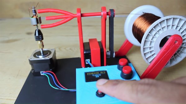
Fortunately there’s a better way, like converting an old outboard motor to electric. It comes to us by way of [Anton], who happened upon the perfect donor platform — a 5-hp outboard by Crescent, sporting a glorious 1970s color scheme and a motor housing shell perfect for modding. He started by ripping the old engine and drivetrain out of the housing to make room for the BLDC motor and its driver. The motor was a project in itself; [Anton] rewound the original stator with much thicker wire and changed the coil configuration to milk as much torque as possible out of it. What started as a 180-kv motor ended up at 77 kv with much more copper and new Hall sensors for the controller. He also put a ton of effort into waterproofing the motor with epoxy resin. With a 3D-printed prop and a streamlined fairing, the new motor looks quite at home on the outboard. In fact, the whole thing barely looks customized at all — the speed control is even right on the tiller where you’d expect it.
The video below shows the build and a test run, plus an analysis of the problems encountered, chief of which is water intrusion. But as [Anton] rightly points out, that’s easily solved by reusing the original driveshaft and mounting the motor above the waterline, like this. Still, we like the look of this, and the idea of knocking around on the water nearly silently seems wonderful.
Continue reading “This Electric Outboard Conversion Makes For A Quiet Day On The Water”