AVR Hardware Timer Tricked Into One-Shot

[Josh] has written up two posts that those of you who use AVRs might find handy. The first post documents a C library that implements a jitter-free one-shot timer. The second post explains how it works. We think it’s such a good idea that we’re going to spoil it for you, but go ahead and read his links and check out his code.

A one-shot is a pulse generator that runs once and only once. You trigger it, it produces the desired pulse, and that’s all she wrote. Why is this handy? Many external ICs that you’ll interface with have minimum durations for signal pulses that must be respected. You could program the AVR to toggle a pin high and then sit around and wait until it’s time to toggle the pin low again, but this wastes valuable CPU time, isn’t going to be very precise, and is susceptible to timing discrepancies if interrupt routines fire in the mean time.

You’d think that you could use the hardware timers for this, but it’s not straightforward. Normally, the timers are free-running; the counter that’s keeping track of time rolls over the top and starts over again. But we just want one pulse.

[Josh]’s very clever idea abuses the timer/counter’s TOP and MATCH values in “Fast PWM” mode. Essentially you trick the counter into never matching by setting TOP below MATCH. This means that the counter spins in its loop between zero and TOP forever, doing nothing.

To break it out of its loop and enable the one-shot, you manually set the counter to a value above TOP and let it go. As it counts up, it’ll eventually hit MATCH, turn on your pin, and then keep counting. When it rolls over the top (255 + 1 = 0 for the 8-bit AVRs), your pin will be correctly turned off again and then the counter re-enters its loop. The one-shot won’t fire until you manually set the counter higher than TOP again.

So there you have it, a one-shot depending only on the hardware timer/counter module and thus immune to jitter and consuming no CPU time at all. Our hats off to you, [Josh]. Clever hack.

Kitchen Timer

A Kitchen Timer Fit For MacGyver

Here’s a project that you don’t want to bring into an airport, ship through the mail, or probably even remove from your home. [ProjectGeek] has built himself a simple kitchen timer masquerading as a bomb. The build is actually pretty simple, but the end result is something that would look at home in a Hollywood action flick.

The timer circuit is built from four simple components. An 8051 microcontroller board is used as the primary controller and timer. The code is available on GitHub. This board is attached to a another board containing four momentary push buttons. These are used to program the timer and to stop the buzzing. Another board containing four 7-segment displays is used to show the remaining time on the timer. A simple piezo buzzer is used to actually alert you when the timer has run out. All of these components are connected with colorful jumper wires.

The physical part of this build is made from easily available components. Old newspapers are rolled up to form the “explosive” sticks. These are then covered in plain brown paper ordinarily used to cover text books. The rolls are bundled together and fixed with electrical tape. The electronics can then be attached to the base with some hot glue or double-sided tape.

HotWheels

DIY Hot Wheels Drag Race Timer

[Apachexmd] wanted to do something fun for his three-year-old son’s birthday party. Knowing how cool race cars are, he opted to build his own Hot Wheels drag race timer. He didn’t take the easy way out either. He put both his electronics and 3D printing skills to the test with this project.

The system has two main components. First, there’s the starting gate. The cars all have to leave the gate at the same time for a fair race, so [Apachexmd] needed a way to make this electronically controlled. His solution was to use a servo connected to a hinge. The hinge has four machine screws, one for each car. When the servo is rotated in one direction, the hinge pushes the screws out through holes in the track. This keeps the cars from moving on the downward slope. When the start button is pressed, the screws are pulled back and the cars are free to let gravity take over.

The second component is the finish line. Underneath the track are four laser diodes. These shine upwards through holes drilled into the track. Four phototransistors are mounted up above. These act as sensors to detect when the laser beam is broken by a car. It works similarly to a laser trip wire alarm system. The sensors are aimed downwards and covered in black tape to block out extra light noise.

Also above the track are eight 7-segment displays; two for each car. The system is able to keep track of the order in which the cars cross the finish line. When the race ends, it displays which place each car came in above the corresponding track. The system also keeps track of the winning car’s time in seconds and displays this on the display as well.

The system runs on an Arduino and is built almost exclusively out of custom designed 3D printed components. Since all of the components are designed to fit perfectly, the end result is a very slick race timer. Maybe next [Apachexmd] can add in a radar gun to clock top speed. Check out the video below to see it in action. Continue reading “DIY Hot Wheels Drag Race Timer”

ATtiny Watering Timer Turns Off The Water When You Forget

ATtiny Water Timer

A pal of [Kyle’s] was regularly leaving his sprinkler on for too long. He also had forgotten to turn the water off while topping off his pool a couple of times, an embarrassing and wasteful situation. Being such a good friend, [Kyle] offered to make him a water timer. This isn’t a regular water timer that turns the water on and off at the same time every day. This device allows the user to push a button to have the unit switch on a solenoid valve, permitting water flow. After a predetermined amount of time the unit removes power to the solenoid valve which stops the water flow, successfully preventing pool overflows and excessive watering.

[Kyle] started off his design using a 555 chip to do the counting. He quickly became worried that timer lengths over 10 minutes would cause inconsistent functionality due to the leakage current of the capacitor and the charge current of the resistor. There are ways around this, but rather than complicate the design he switched to an ATtiny microcontroller. The added benefit of the ATtiny is that he could connect up a potentiometer to adjust the on-time without replacing parts or making a new unit. When the potentiometer is turned, the on-board LED will flash a number of times which corresponds with the delay in minutes. Ten flashes means a 10 minute delay. It’s a simple and clear interface.

As if the home etched PCB wasn’t cool enough, [Kyle] 3D printed up a case for the unit. The case permits access to the screw terminals and has provisions for the indicator LEDs. Check out the integrated flap in the top of the case. When this portion of the case is pushed in, it presses the PCB-mounted on/off switch.

If you are interested in making one, all of the files and code are available on [Kyle’s] site.

via [dangerous prototypes]

Hacklet #8: The Animals

8

This week on the Hacklet we’re looking at Hackaday.io projects that are all about animals! Hackers and makers are well-known animal lovers, in fact many a hacker can be found with a pet curled up at their feet, or on their keyboard!

catWater
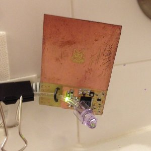
[Brian’s] cat Roger loves drinking from the bathtub faucet. Unfortunately Roger hasn’t learned how to operate the faucet himself, so it gets left on quite a bit. To keep Roger happy while saving water, [Brian] created the Snooty Cat Waterer. Cat’s still don’t have thumbs, so [Brian] turned to capacitive sensing in the form of a Microchip MTCH10 capacitive proximity sensor chip. Coupled with a home etched PC board, the waterer can detect a cat at 3 inches. A valve and water feed teed off the toilet provide the flow. The project is moving along well, though Roger has been slow to warm up to this new water source.


catWater2
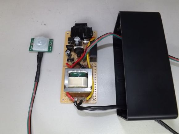
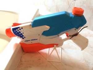
[Jsc] has the opposite problem. His cat has decided that bathtubs are the perfect litter boxes. [Jsc] is taking aim at this little problem with his Cat Dissuader. After a servo controlled squirt bottle proved too anemic for his needs, [Jsc] turned to the Super Soaker Hydrostorm. These electric water guns can be had for as little as $16 on sale. [JSC] didn’t want to permanently modify the gun, so he 3D printed a switchable battery pack.The replacement pack is actually powered by a simple wall wart. Power to the gun is controlled by an Arduino, which senses his cat with a passive infrared sensor. Since the dissuader was installed, [Jsc’s] cat has been a model citizen!


doggieBowl
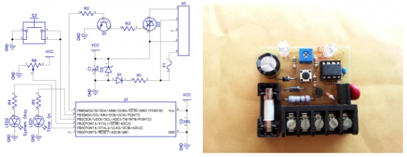
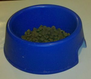
Cat’s don’t get all the love though, plenty of engineers and hackers have dogs around the house. [Colin] loves his dog, but he and his family were forgetting to feed it. He created Feed the Dog to help the household keep its four-legged member from going hungry. [Colin] tried a microcontroller, but eventually settled on implementing the circuit with old-fashioned 4000 series CMOS logic chips. He used a 4060 (14-stage ripple counter w/ internal oscillator) as an 8 hour timer, and 4013 dual flip-flop. Operation of Feed the Dog is as simple as wagging your tail. Once the dog is feed, the human presses a button. A green “Just fed” LED will glow for 30 minutes, then go dark. After about 6 hours, a red LED turns on. After 8 hours, the red LED starts blinking, letting everyone know that it’s time to feed the dog.


chookin

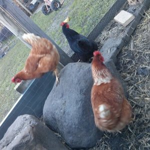
[Steve] has outdoor pets. Chooks to be exact, or chickens for the non Australians out there. He loves watching his birds, especially Darth Vader, who is practicing to become a rooster. To keep track of the birds, he’s created What the Chook?, a sensor suite for the hen-house. He’s using a GCDuiNode with a number of sensors. Temperature, humidity, even a methane detector for when the bedding needs to be replaced. An OV528 JPEG camera allows [Steve] to get pictures of his flock. The entire project connects via WiFi. Steve hopes to power it from a couple of AA batteries. [Steve] also entered What the Chook? in The Hackaday Prize. If he wins, this will be the first case of flightless birds sending a human to space!


hackaspace-mini

Hey – Did you know that Hackaday is building a Hackerspace in Pasadena California? We’re rounding up the local community while our space is being built out. Join us at a Happy Hour Show & Tell Meetup Event hosted by our own [Jasmine Brackett] August 18th! It’s an informal show and tell, so you don’t have to bring a hack to attend. If you’re local to Pasadena, come on down and say hello!


A Motion Activated AC Switching Circuit Using Mostly Discrete Components

AC motion switch

If you’ve ever dealt with a brightly lit Christmas tree, you might understand the frustration of having to crawl underneath the tree to turn the lights on and off. [brmarcum] feel’s your pain. He’s developed his own motion activated AC switching circuit to turn the lights on and off automatically. A motion sensor ensures that the lights are only on when there are people around to actually see the lights. The circuit also has an adjustable timer so [brmarcum] can change the length of time that the lights stay on.

The project is split into several different pieces. This makes the building and debugging of the circuit easier. The mains power is first run through a transformer to lower the voltage by a factor of 10. What remains is then filtered and regulated to 9VDC. [brmarcum] is using a Parallax PIR sensor which requires 4.5V. Therefore, the 9V signal is then lowered once more using a voltage divider circuit.

When the PIR sensor is triggered, it activates the timer circuit. The timer circuit is driven by a 555 timer. The circuit itself was originally borrowed from a classic Forrest Mims book, though it was slightly modified to accommodate the PIR sensor. The original push-button trigger was removed and replaced with the signal from the PIR sensor. The only problem is that the circuit was expecting a low signal as the trigger and the PIR sensor outputs a high signal. [brmarcum] resolved this problem with an NPN BJT to invert the signal. Once the timer is triggered, it flips on a relay that allows the mains electricity to flow through to the lights.

[brmarcum] soldered the entire circuit onto a piece of protoboard. The final product was then mounted securely inside of an insulated plastic case. This allows him to mount the circuit safely underneath the Christmas tree skirt. The PIR sensor is kept external to the enclosure and wired up into the tree itself. This allows the sensor to still detect motion in the room while the rest of the circuit is hidden away.

[via Reddit]

The Un-Digital Robotic Arm

556When you think of a robotic arm, you’re probably thinking about digital control, microcontrollers, motor drivers, and possibly a feedback loop. Anyone who was lucky enough to have an Armatron knows this isn’t the case, but you’d still be surprised at how minimal a robotic arm can be.

[viswesh713] built a servo-powered robotic arm without a microcontroller, and with some interpretations, no digital control at all. Servos are controlled by PWM signals, with a 1 ms pulse rotating the shaft one way and a 2 ms pulse rotating the shaft the other way. What’s a cheap, popular chip that can easily be configured as a timer? Yep, the venerable 555.

The robotic arm is actually configured more like a Waldo with a master slave configuration. [viswesh] built a second arm with pots at the hinges, with the resistance of the pots controlling the signal output from a 556 dual timer chip. It’s extremely clever, at least until you realize this is how very early robotic actuators were controlled. Still, an impressive display of what can be done with a simple 555. Videos below.

Continue reading “The Un-Digital Robotic Arm”