Grinding Gears: Figuring Out The Ratio

Practically any combination of motor and gearbox can be mathematically arranged to fit all sorts of problems. You could lift a crane with a pager motor, it just might take a few hundred years. However, figuring out exactly what ratio you need can feel bit backwards the first time you have to do it.

A gear is nothing more than a clever way to make two circles rotate in concert with each other as if they were perfectly joined at their circumferences. Rather than relying on the friction between two rotating disks in contact, the designer instead relies on the strength of a gear tooth as the factor limiting the amount of torque that can be applied to the gear.

Everything is in gearing is neatly proportional. As long as your point of reference is correct, and some other stuff. Uh, it gets easier with practice.

\frac{radius_1}{radius_2} = \frac{velocity_1}{velocity_2} = \frac{tangentialforce_1}{tangentialforce_2} = \frac{torque_1}{torque_2}

Now as my physics professors taught me to do, let’s skip the semantics and spare ourselves some pedantics. Let us assume that all gears have a constant velocity when you’ve averaged it all out. Sure there is a perceptible difference between a perfect involute and a primitive lantern gear, but for the sake of discussion it doesn’t matter at all. Especially if you’re just going to 3D print the thing. Let’s say that they’re sitting on perfect bearings and friction isn’t a thing unless we make it so. Also we’ll go ahead and make them perfectly aligned, depthed, and toleranced.

Typically, a gearbox is used for two things. You have a smaller torque that you’d like to make into a bigger one or you have one rotational velocity that you’d like to exchange for another.  Typically torque is represented with a capital or lowercase Tau (Ττ) and rotational velocity likes to have a lowercase omega (ω). It also doesn’t matter at all; it just makes your equations look cooler.

Now a lot of tutorials like to start with the idea of rolling a smaller circle against a bigger one. If the smaller circle is a third as large as the big one, it will take three rotations of the small circle to make the big one rotate twice.  However, it is my opinion that thinking it in terms of the force applied allows a designer to think about the gearing more effectively.

path3338

If the friction between the two surfaces of the circle is perfect, then any force applied tangentially to one of the circles will result in a perfectly perpendicular and equal force to the other circle at the point of contact between the two. Midway through writing the preceding sentence I began to understand why textbooks are so abstruse, so I also drew a picture. This results in two equations.

 \tau_1 = F * r_1 

\tau_2 = F * r_2  

Evernote Snapshot 20160831 181223
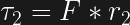
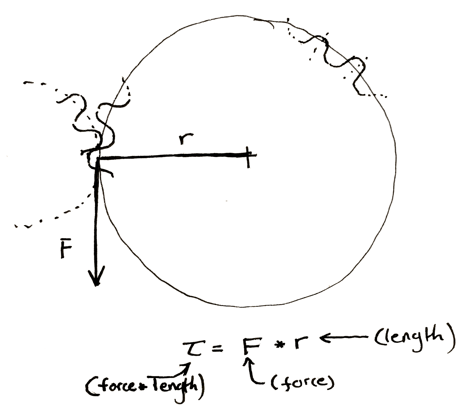
Now, when you have a force perpendicular to the line drawn to describe the radius, the equation for torque becomes really simple.

Multiply the length of the “lever arm”, “radius”, etc. by the force to get the preceding equations. Make sure to include the units.

You should end up force-unit * length-unit. Since I usually work in smaller gears I like to use N * mm. American websites typically use oz-in to rate motors. It is technically ozf-in (ounce-force), but the US customary system has a fetish for obtuseness.

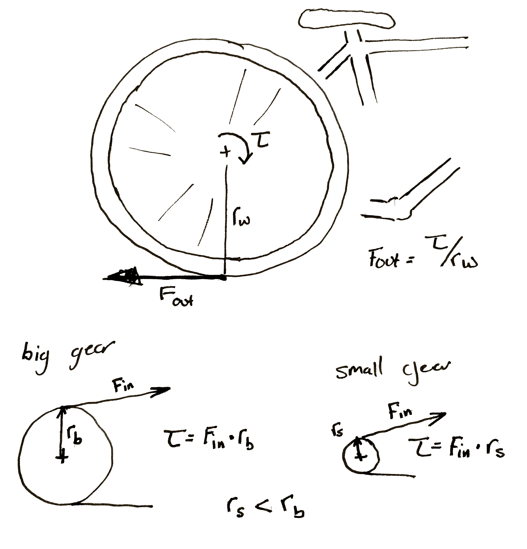
We can make some observations. The smaller gear always sees less torque at its center. This initially seemed a bit counter-intuitive to me. If I’m using a cheater bar to turn a bolt the longer I make the bar the more torque I can put on the bolt. So if I touch the outside of a really large gear I should be seeing a ton of torque at the center of a small gear rotating along with it. However, as we mentioned before, any torque applied on the outside of the larger gear is seen equal and tangential on the smaller. It’s as if you’re touching the outside of the small gear. The torque has to be smaller.

This is why you have to pedal so much harder when the rear sprocket on a bicycle gets smaller.  Each time you make the sprocket smaller you shrink the torque input into the wheel. If the perpendicular output where the wheel hits the ground is <input from the small gear> / <radius of the wheel> then it’s obvious why this happens.

Hopefully my diagram doesn't win a prize for awfulness. Then again, an award's an award.
Hopefully my diagram doesn’t win a prize for awfulness. Then again, an award is an award. Remember that the bicycle wheel and  its input gear are rigidly attached to each other.

It’s also important to note that any time you increase the torque, the speed of the gears slow by the same proportion. If you need 60 N*m out of a motor that can give 20 N*m and you use a 3:1 gearbox to do it. If the motor previously ran at 30 rpm it’s now running at 10 rpm.

Let’s jump right into an example. Let’s say you want to make a device that automatically lifts your window blinds. You’ve got some junk and a 3D printer.

The problem set-up.
The problem set-up.

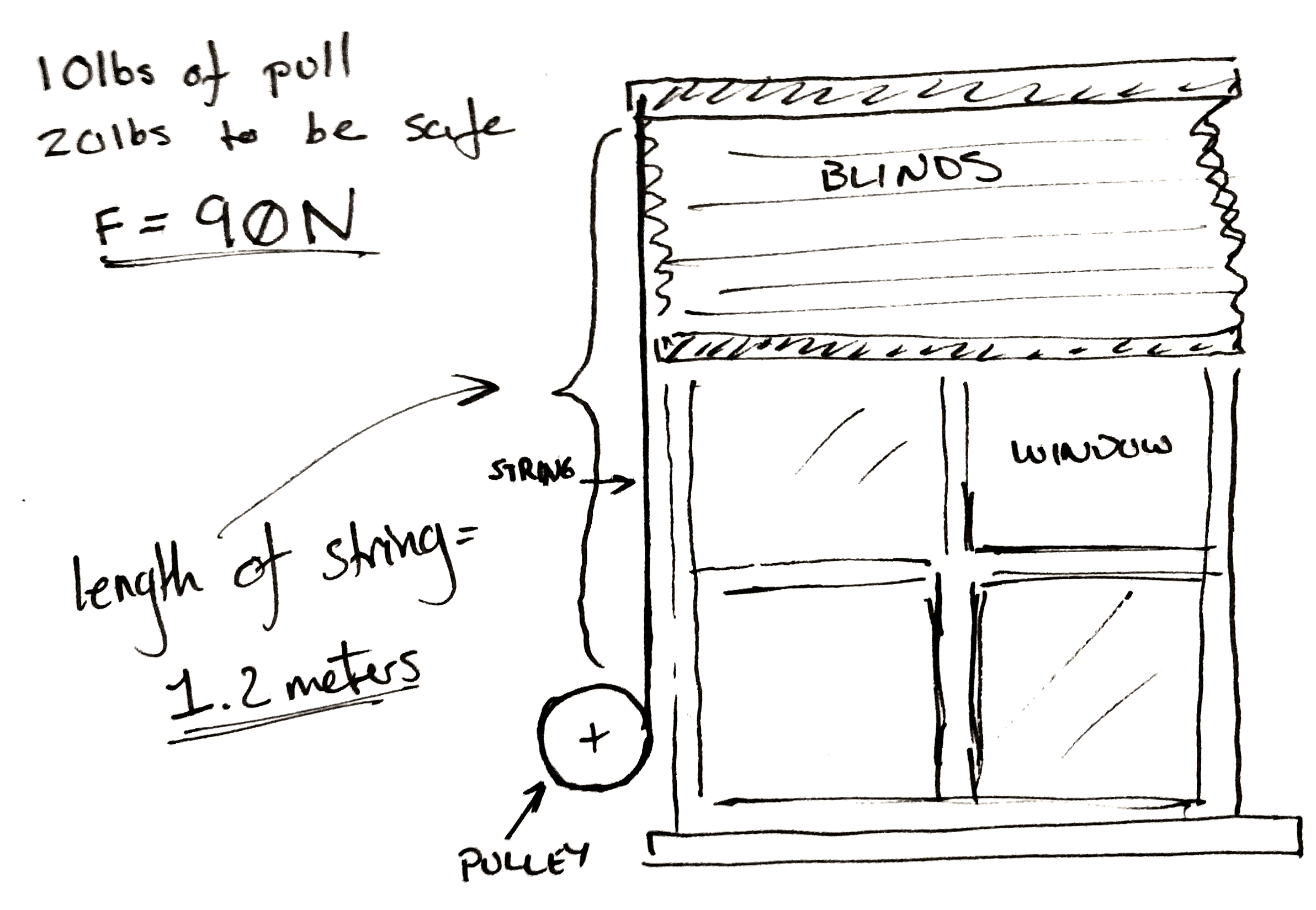
Now you’ve taken a spring scale and pulled until the shutter moves and you know you need 10 lbs. of pull to get the blinds to pull up. To make it easy on yourself you multiply this number by two so you know you need exactly 20 lbs of force to pull the curtain up. Then to make it really easy on yourself convert it all to Newtons. It’s approximately 90 N.

Now you don’t really care how fast the blinds pull up, but you go ahead and pull them up yourself. You get the feeling that the blinds won’t appreciate being lifted faster than the whole range in two seconds. You personally don’t care if takes ten seconds to, but you’d like it not to take too long.

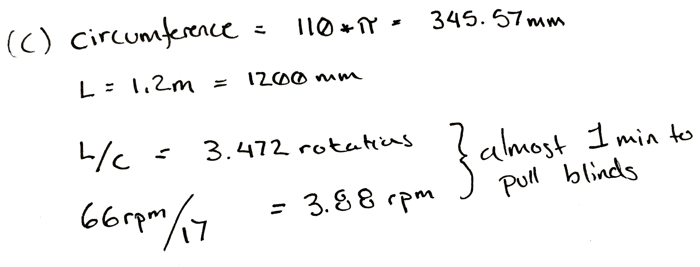
You also measure the length of string pulled out to raise the blinds. It’s 1.2 meters.

A classic. Cheap. Unreliable. Weak. Also Cheap.
A classic.

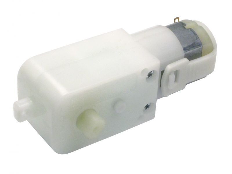
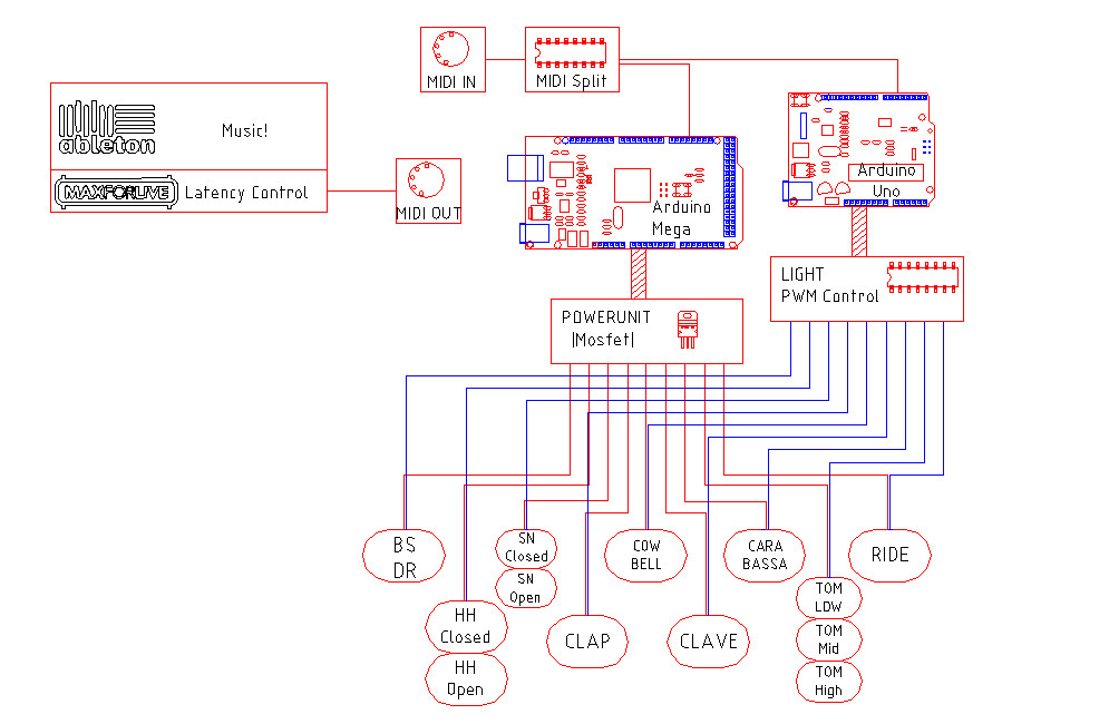
Lastly, you only have one spare power supply and a matching motor left in your entire laboratory after you followed the advice in a Hackaday article. Cursing the day the author was born, you sullenly write down the last specifications. You’ve got one of those cheap GM9 gear motors. 5 V, 66 rpm, and 300 N*mm. You damn him as you think fondly of your mountain of windshield washer motors and 80 lb server rack power supplies that you tossed out.

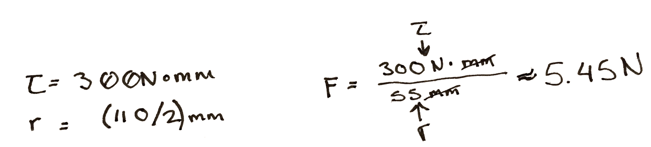
To start with, you do some experiments with a pulley. You arbitrarily pick, 3D print, and find that a 100 mm in diameter pulley seems to wind it up nicely by hand. By the end of the winding the outside diameter of the string is 110 mm. So you use the torque equations above. You find that at the end of the rotation, if you attach the motor directly, there is only 5.45 N of force being applied to the string. Not nearly enough.

Hrm..
Hrm..

So, since you know everything is more or less proportional, you divide 90 N / 5.45 N, and arrive at an answer of 17. So, at a minimum for every turn of the pulley you need 17 turns of the motor to get the torque needed.

That would be okay, but it messes with our other specification. At a 17:1 ratio, it will take our 66 rpm motor pretty close to a minute to wind the blinds up.

Damn.
Damn.

This is a moment for some pondering. Make a coffee. Maybe go write a relaxing comment to a Hackaday writer listing their various flaws, perceived and true, in excruciating detail.

What if you wound the string up on a closet rod? Those are only about 30 mm in diameter. You take a bit of rod and wind it up. It seems to work and since it’s wider the string only ends up adding 5 mm to the final diameter. You rework the calculation and find that in this case you only need a ratio of 6! Yes.

Now some of you who have done this before are likely gnashing your teeth, or more likely already down in the comments. Unfortunately it’s all proportional. While you only need a ratio of 6:1 now, nearly a third. You also need to rotate the pulley approximately three times as much to pull the same length of cord.

Sometimes you can’t win. In this case the only solution is to order a new motor. You look online for a bit and realize that one of the 12 V motors you threw away last week would work perfectly for this. You wouldn’t even need a gear box. You could attach it straight to the pulley. You look around your perfectly clean and orderly garage and feel empty.

However, just for fun you build a 6:1 gearbox anyway. It’s a hack after all.

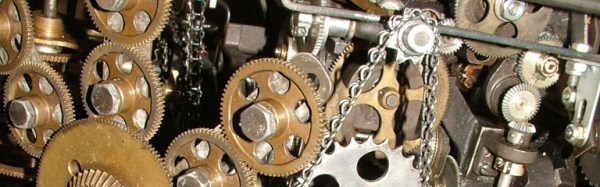
Cover photo of the hilariously complicated Do Nothing Machine credit to the Joe Martin Foundation.

Real-Life Space Invaders With Drones And Lasers

We’ve seen a proliferation of real-life video game builds lately, but this one is a jaw-dropper! [Tomer Daniel] and his crew of twelve hackers, welders, and coders built a Space Invaders game for GeekCon 2016.

[Tomer] et al spent more time on the project than the writeup, so you’re going to have to content yourselves with the video, embedded below, and a raft of photos that they sent us. ([Tomer] wrote in and wanted to thank each of you, and his sponsors, by name, but that would be a couple paragraphs on its own. Condider yourselves all thanked!)
Continue reading “Real-Life Space Invaders With Drones And Lasers”

Preparing Your Product For The FCC

At some point you’ve decided that you’re going to sell your wireless product (or any product with a clock that operates above 8kHz) in the United States. Good luck! You’re going to have to go through the FCC to get listed on the FCC OET EAS (Office of Engineering and Technology, Equipment Authorization System). Well… maybe.

As with everything FCC related, it’s very complicated, there are TLAs and confusing terms everywhere, and it will take you a lot longer than you’d like to figure out what it means for you. Whether you suffer through this, breeze by without a hitch, or never plan to subject yourself to this process, the FCC dance is an entertaining story so let’s dive in!

Continue reading “Preparing Your Product For The FCC”

New Part Day: A Truly Secure Workstation

There is a chain of trust in every modern computing device that starts with the code you write yourself, and extends backwards through whatever frameworks you’re using, whatever OS you’re using, whatever drivers you’re using, and ultimately whatever BIOS, UEFI, Secure Boot, or firmware you’re running. With an Intel processor, this chain of trust extends to the Intel Management Engine, a system running independent of the CPU that has access to the network, USB ports, and everything else in the computer.

Needless to say, this chain of trust is untenable. Any attempt to audit every line of code running in a computer will only be met with frustration. There is no modern Intel-based computer that is completely open source, and no computer that can be verified as secure. AMD is just as bad, and recent attempts to create an open computing platform have met with frustration. [Bunnie]’s Novena laptop gets close, but like any engineering task, designing the Novena was an exercise in compromise. You can get around modern BIOSes, coreboot still uses binary blobs, and Libreboot will not be discussed on Hackaday for the time being. There is no modern, completely open, completely secure computing platform. They’re all untrustworthy.

The Talos Secure Workstation, from Raptor Engineering, an an upcoming  Crowd Supply campaign is the answer to the untrustworthiness of modern computing. The Talos is an effort to create the world’s first libre workstation. It’s an ATX-compatible motherboard that is fully auditable, from schematics to firmware, without any binary blobs.

Continue reading “New Part Day: A Truly Secure Workstation”

Real, Life-Sized Transformers

Ever dreamed of a real, life-sized Transformer in your garage? The Turkish startup Letrons now offers you exactly that: Their animatronic Autobot drives like a car, transforms like a Transformer, and supposedly fights off space threats with its built-in smoke machine and sound effects.

Letrons’s Transformer seems to be built upon a BMW E92 coupé chassis. According to the company, the beast is packed with powerful hydraulics and servo motors, allowing it to transform and move fast. Sensors all around the chassis give it some interactivity and prevent it from crushing innocent bystanders when in remote-control mode. Interestingly, its movable arms aren’t attached to the body, but to its extendable side-wings and feature hands with actuated wrists and fingers. The Autobot also can move its head, which pops right out of the hood.

Admittedly, Letrons must have spent a lot of time on the dark side of the moon and working in secrecy before they released footage of a working and polished prototype. It’s unclear if Letron’s Transformers will cooperate with the US military in solving armed conflicts, but they are certainly good for a show. Enjoy the video below!

Continue reading “Real, Life-Sized Transformers”

Hackaday Prize Entry: Text To Speech The Hard Way

Studies have shown reading to children leads to improved academic performance later in life, a trait that will make them more competitive in the workforce, and ultimately happier human beings. It follows, then, that having a robot read to children will also lead to happier and more productive adults, while normalizing the cyborg uprising takeover of the AI apocalypse of 2037.

It’s a good thing the above paragraph is a complete non-sequitur and has nothing to do with this Hackaday Prize entry. The TextEye, [Markus]’ entry for the Assistive Technology portion of the Hackaday Prize, is a handheld device that translates the written word into speech, useful for anyone who either can’t see well or can’t read gooder. Yes, it will also read to children, but so did Teddy Ruxpin.

If you’re keeping track, this isn’t the first time [Markus] has entered this project in a Hackaday Prize contest. The first time was six months ago in the Hackaday / Adafruit Raspberry Pi Zero contest. [Markus] was inspired by a group of blind computer science students using specialized hardware that allowed them to study the same thing as everyone else.

Since the first few project logs, a lot has changed in this project. You can buy a Pi Zero easily, and the updated Pi Zero 1.3 now comes with a camera connector. [Markus] is swapping out his Pi Model A and USB webcam for the Pi Zero and Pi camera. The software remains the same — GraphicsMagick, Tesseract OCR, Festival and Wiring Pi handle reading text and turning those words into speech — with a slight refactoring of the code. It’s a great use for the Pi Zero, and an excellent example of an Assistive Technology, and we’re happy to see it again in the Hackaday Prize.

A Robotic 808 Drum Machine

If you spent the 1980s hanging out at your local record store, and you don’t have a hankering for spandex and bouffant rock-god hairstyles, the chances are you’ll have more than a few pieces of electronic music from the period in your collection. The proliferation of electronica during that era came through the arrival of relatively inexpensive mass-market digital polyphonic instruments, edging out the sounds of monophonic analog synthesisers for a subsequent generation to rediscover in a later decade. Individual instrument models became icons and entered the musical vernacular of the day, the Ensoniq Mirage sampling synthesiser, the Yamaha DX7 FM synthesiser, or the Roland TR-808 drum machine.

It is the Roland TR-808 that inspired today’s subject, the MR-808 robotic drum machine, from [Moritz Simon Geist]. A percussion sequencer featuring real instruments all built into a cabinet styled to resemble a huge Roland 808. Originally built as a performance instrument, but since reinvented as a piece of installation artwork that visitors can program for themselves.

Block diagram of the MR-808

There is a comprehensive description of the machine’s design and build on the creator’s website, as well as a more high-level introduction. A significant amount of effort was put in to creating mechanical instruments as close as possible to the Roland sounds, with each instrument being operated by solenoids driven by a MIDI-controlled Arduino Mega. A second Arduino, this time an Uno, controls lighting that follows the instruments.

The interactive part of the installation comes from a sequencer front-end running in a web browser on a Nexus 7 tablet, this appears to be served from a Raspberry Pi which supplies MIDI to the MR-808.

The results can be seen in the video below the break, and judging by the reaction of the audience the machine is rather popular.

Continue reading “A Robotic 808 Drum Machine”