Cheap DIY MIDI To USB Adapter

[Joonas] became frustrated with cheap but crappy MIDI to USB converters, and the better commercial ones were beyond his budget. He used a Teensy LC to build one for himself and it did the job quite well. But he needed several converters, and using the Teensy LC was going to cost him a lot more than he was willing to spend. With some tinkering, he was able to build one using an Adafruit Pro Trinket which has onboard hardware UART (but no USB). This lack of USB support was a deal killer for him, so after hunting some more he settled on a clone of the Sparkfun Pro Micro. Based on the ATmega32U4, these clones were just right for his application, and the cheapest to boot. He reckons it cost him about $5 to build each of his cheap USB MIDI adapters which receive notes and pedal data from the keyboard’s MIDI OUT and transmit them to a computer

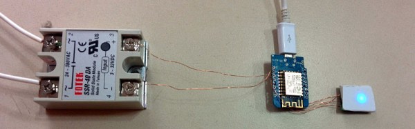
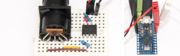
Besides the Pro Micro clone, the only other parts he used are a generic opto-coupler, a couple of resistors and a MIDI connector. After testing his simple circuit on a bread board, he managed to squeeze it all inside an old USB dongle housing, stuffing it in dead-bug style.

The heavy lifting is all done in the firmware, for which [Joonas] used LUFA — the Lightweight USB Framework for AVR’s. He wrote his own code to handle MIDI (UART) to USB MIDI messages conversion. The interesting part is his use of a 32.15 kbps baud rate even though the MIDI specification requires 31.25 kbps. He found that a slightly higher baud rate fixes a problem in the AVR USART implementation which tends to miss consecutive bytes due to the START edge not being detected. Besides this, his code is limited in functionality to only handle a few messages, mainly for playing a piano, and does not have full-fledged MIDI capabilities.

We’ve featured several of [Joonas]’s hacks here over the years, the most recent being the Beaglebone Pin-Toggling Torture Test and from earlier, How to Turn A PC On With a Knock And An ATTiny.

Adaptive guitar: pick board and controller

Hackaday Prize Entry: Adaptive Guitar

Due to a skiing accident, [Joe]’s new friend severed the motor nerves controlling her left arm. Sadly she was an avid musician who loved to play guitar — and of course, a guitar requires two hands. Or does it? Pressing the string to play the complex chords is more easily done using fingers, but strumming the strings could be done electromechanically under the control of a foot pedal. At least that’s the solution [Joe] implemented so beautifully when his friend’s family reached out for help.

There are just so many things to enjoy while reading through [Joe]’s project logs on his hackaday.io page, which he’s entered into the Hackaday Prize. He starts out with researching how others have solved this problem. Then he takes us through his first attempts and experiments. For example, an early discovery is how pressing the strings on the fretboard pulls the string down where the picks are located, causing him to rethink his initial pick design. His criteria for the pick actuators leads him to make his own. And the actuators he made are a thing of beauty: quiet, compact, and the actuator body even doubles as part of a heat sink for his custom controller board. During his pick design iterations he gets great results using spring steel for flexibility leading up to the pick, but thinking of someday going into production, he comes up with his own custom-designed, laser-cut leaf springs, different for each string.  Needing Force Sensitive Resistors (FCRs) for the foot pedal, he iterates to making his own, laying out the needed interlinked traces on a PCB (using an Eagle script) and putting a piece of conductive rubber over it all. And that’s just a sample of the adventure he takes us on.

In terms of practicality, he’s made great efforts to make it compact and easy to set up. The foot pedal even talks to the control board on the guitar wirelessly. Non-damaging adhesives attach magnets and velcro to the guitar so that the control board and pick bridge can be precisely, yet easily, attached single-handedly. The result is something easy to manage by someone with only one working hand, both for set-up and actual playing. See it for yourself in the video below.

Continue reading “Hackaday Prize Entry: Adaptive Guitar”

Return To The Asus Tinker Board: Have Six Months Changed Anything?

The Asus Tinker Board, in all its glory

Back in February this year, we ordered a new single board computer, and reviewed it. The board in question was the Asus Tinker Board, a Raspberry Pi 3 competitor from the electronics giant in a very well-executed clone of the Raspberry Pi form factor.

Our review found its hardware to be one of the best of that crop of boards we had yet seen, but found serious fault with the poor state of its software support at the time. There was no website, the distro had to be downloaded from an obscure Asus download site, and there was no user community or support channel to speak of. We were then contacted by some of the folks from Asus who explained that the board had not yet been officially launched, and that the unit we’d secured had escaped the fold a little early. Continue reading “Return To The Asus Tinker Board: Have Six Months Changed Anything?”

Photo by Todd Bakken

Sector67 Hackerspace Rocked By Explosion At New Location

Madison, WI hackerspace Sector67 is in a period of transition as they move from their current rented location to a new property that will be their permanent home a half mile away. Last Wednesday (September 20, 2017) an unfortunate propane explosion in the new building led to the injury of Chris Meyer, the founder and director of the hackerspace.

The structure has been stabilized and renovation is continuing, but Chris was seriously burned and will be in the hospital for at least a month with a much longer road to complete recovery. It is fortunate that nobody else was injured.

This accident comes at a time when Sector67 essentially has two spaces to maintain; the existing space is still running, but many of the members are focused on the construction of the new space. The building needs significant work before the move can take place. Currently the roof is being raised so that the building can go from one awkward-height story to two normal stories, doubling the size. An expiring lease and imminent demolition of the current location by developers means the clock is still ticking on the move, and this explosion means Sector67 will have to work even harder, and without the presence and constant effort of the person who has been leading the project.

A GoFundMe campaign for Sector67 has been started and is well on its way towards helping Chris and Sector67.

An Introduction To Solid State Relays

When we think of relays, we tend to think of those big mechanical things that make a satisfying ‘click’ when activated. As nice as they are for relay-based computers, there are times when you don’t want to deal with noise or the unreliability of moving parts. This is where solid-state relays (SSRs) are worth considering. They switch faster, silently, without bouncing or arcing, last longer, and don’t contain a big inductor.

Source Fotek SSR Specifications Sheet

An SSR consists of two or three standard components packed into a module (you can even build one yourself). The first component is an optocoupler which isolates your control circuit from the mains power that you are controlling. Second, a triac, silicon controlled rectifier, or MOSFET that switches the mains power using the output from the optocoupler. Finally, there is usually (but not always) a ‘zero-crossing detection circuit’. This causes the relay to wait until the current it is controlling reaches zero before shutting off. Most SSRs will similarly wait until the mains voltage crosses zero volts before switching on.

If a mechanical relay turns on or off near the peak voltage when supplying AC, there is a sudden drop or rise in current. If you have an inductive load such as an electric motor, this can cause a large transient voltage spike when you turn off the relay, as the magnetic field surrounding the inductive load collapses. Switching a relay during a peak in the mains voltage also causes an electric arc between the relay terminals, wearing them down and contributing to the mechanical failure of the relay.

Continue reading “An Introduction To Solid State Relays”

Chess Robot’s Got The Moves

[RoboAvatar]’s Chess Robot consists of a gantry-mounted arm that picks up chess pieces and places them in their new location, as directed by the software. The game begins when the human, playing white, makes a move. When a play has been made, the human player presses a button to let the robot to take its turn. You can see it in action in the videos we’ve posted below the break.

Running the robot is an Arduino UNO with a MUX shield as well as a pair of MCP23017 I/O expander chips — a total of 93 pins available! Thanks to all those pins, the Arduino is able to listen to 64 reed switches, one for every square.

The robot detects the human’s move by listening to its reed switches and identifying when there is a change. The gantry consists of X and Y tracks made out of PVC slabs, with half-inch lead screws turned by NEMA-23s and powered by ST-6600 stepper drivers.

Unlike some chess robots that rely on pre-existing software, this one features a custom minimax chess algorithm that [RoboAvatar] coded himself. It consists of Python scripts run on a computer, which interacts with the Arduino via a serial connection. In the second video, he explains how his algorithm works. You can also download the Arduino and Python files from [RoboAvatar]’s GitHub repository.

You’d be surprised how many chess-playing robots we’ve published, like the ChessM8 robot and this voice-controlled chess robot.

Continue reading “Chess Robot’s Got The Moves”

Emulate ICs In Python

Most people who want to simulate logic ICs will use Verilog, VHDL, or System Verilog. Not [hsoft]. He wanted to use Python, and wrote a simple Python framework for doing just that. You can find the code on GitHub, and there is an ASCII video that won’t embed here at Hackaday, but which you can view at ASCIInema.

Below the break we have an example of “constructing” a circuit in Python using ICemu:

Continue reading “Emulate ICs In Python”