Copper is a material with many applications; typically, it’s used for electrical wiring or in applications where good heat conductivity is a requirement. However, it can also make for an attractive material in furnishings, which [Andrei Erdei] decided to explore.
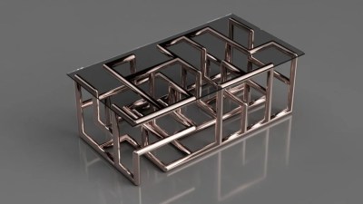
A render of the coffee table design, exported from OpenSCAD into Fusion360.
[Andrei]’s work began in OpenSCAD, where he wrote scripts to enable the quick and easy assembly of various designs. The modular nature of commercially-available copper pipe and fittings allows complex structures to be assembled, particularly if you’re a fan of 90-degree bends. The final renders of some of these designs are impressive, with the coffee table design a particular highlight. Staying conceptual wasn’t enough, however, so [Andrei] set out to build one of his designs. Constructing a table lamp shroud out of copper parts was successful, though the real components have flanges and other features that aren’t represented in the rendering.
It’s a project that shows the value of tools such as OpenSCAD to aid the design process before committing to cutting real-world materials. While the designs on screen aren’t perfect representations of what’s possible in reality, it still proves to be a useful guide.
We’re a fan of the aesthetic, and would love to see more done with copper pipe as a construction kit. Global ore prices may limit experimentation, however. Alternatively, you can always harvest the metal from scrap!
Erika’s origin story begins with an interest in electronics during her teenage years that led to work in recording studios. It seems nobody on staff there was interested in repairing anything. Every company needs a hacker to make sure everything continues to work and she decided to take on the role.
From there Erika found her way into the world of manufacturing and has never looked back. You may remember hearing some of her experiences in her 2016 Hackaday Supercon talk on turning your manufacturing mistakes in a learning experience. During this panel she recounts one particularly painful experience when over-torque on a six-layer PCB damaged traces and led to extensive manual rework; always include a torque-spec!
In addition to driving home the need for Steadicam or Optical Image Stabilization, this eighty-year-old video illustrates some elegant solutions the automotive industry developed in their suspension systems. Specifically, this Chevrolet video from 1938 is aimed at an audience that values science and therefore the reel boils down the problem at hand using models that will remind you of physics class.
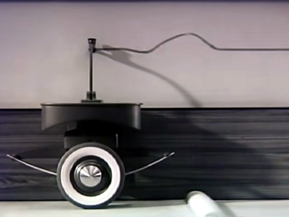
Model of a wheel with a leaf spring records the effect of a bump on a piece of paper above
The problem is uneven ground — the “waves in the Earth’s surface” — be it the terrain in an open field, a dirt road, or even a paved parkway. Any vehicle traveling those surfaces will face the challenge of not only cushioning for rough terrain, but accounting for the way a suspension system itself reacts to avoid oscillation and other negative effects. In the video this is boiled down to a 2-dimensional waveform drawn by a model which begins with a single tire and evolves to include a four wheeled vehicle with different suspension systems in the front and the rear.
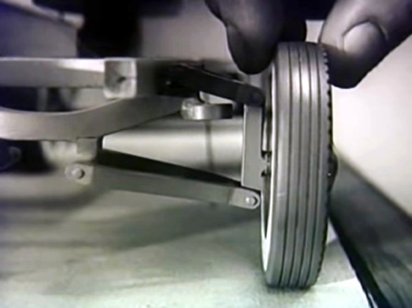
Perhaps the most illuminating part of the video is the explanation of how the car’s front suspension actually works. The wheels need to be able to steer the vehicle, while the suspension must also allow the tire to remain perpendicular to the roadway. This is shown in the image at the top of this article. Each wheel has a swing arm that allows for steering and for vertical movement of the wheel. A coil spring is used in place of the leaf springs shown in the initial model.
You probably know what’s coming next. The springs are capable of storing and releasing energy, and left to their own devices, they’ll dissipate the energy of a bump by oscillating. This is exactly what we don’t want. The solution is to add shock absorbers which limit how the springs perform. The waveforms drawn by the model encountering bumps are now tightly constrained to the baseline of flat ground.
This is the type of advertising we can wholeheartedly get behind. Product engineers of the world, please try to convince your marketing colleagues to show us the insides, tell us why the choices were made, and share the testing that helps users understand both how the thing works and why it was built that way. The last eighty years have brought myriad layers of complexity to most of the products that surround us, but human nature hasn’t changed; people are still quite curious to see the scientific principles in action all around us.
Make sure you don’t bomb out of the video before the very end. A true bit of showmanship, the desktop model of a car is recreated in a full-sized Chevy, complete with “sky-writing smoke” to draw the line. I don’t think it’s a true analog, but it’s certainly the kind of kitsch I always look for in a great Retrotechtacular subject.
[Elite Worm] wrote in to tell us about a cool little keyboard designed to make playing a certain game a whole lot easier. One of the ways you can move your character is with the numpad in directional mode plus Control and Shift, but those are too far apart to drive blindly with one hand. This is all the motivation [Elite Worm] needed to build a custom keyboard with only the essentials.
The keyboard is controlled by an Arduino Pro Micro, which is fairly standard for this type of build — it’s usually that or a Teensy. [Elite Worm] used Cherry MX browns for a nice tactile feel, and added LEDs for a purple-white under-glow. We love the way the printed keycaps turned out, and are impressed because tolerances are notoriously tight for those fruity switch stems.
Starting to think of a few uses for a small custom keypad? This thing is wide open, and [Elite Worm] will even send you the PCB files if you ask nicely. See if you can get past the break without your mouse, and check out the build video while you wait.
But of course these smart speakers are listening all the time, at least locally. How else are they going to know that someone uttered one of their wake words, or something close enough? It would sure help a lot if we could change the wake word to something like ‘rutabaga’ or ‘supercalifragilistic’, but they probably have ASICs that are made to listen for a few specific words. On the Echo for example, your only choices are “Alexa”, “Amazon”, “Echo”, or “Computer”.
So how often are smart speakers listening when they shouldn’t? A team of researchers at Boston’s Northeastern University are conducting an ongoing study to determine just how bad the problem really is. They’ve set up an experiment to generate unexpected activation triggers and study them inside and out.
The Raspberry Pi camera has become a de facto standard for many maker projects, making things like object recognition and remote streaming a breeze. However, the Sony IMX219 camera module used is capable of much more, and [Gaurav Singh] set out to unlock its capabilities.
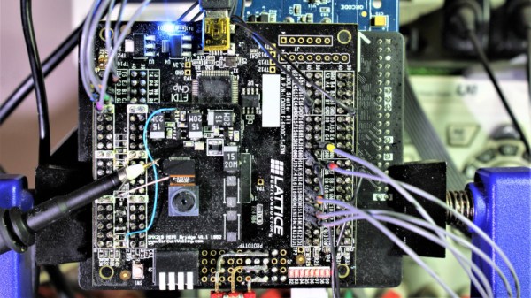
After investigating the IMX219 datasheet, it became clear that it could work at higher bandwidths when configured to use all four of its MIPI CSI lanes. In the Raspberry Pi module, only two MIPI lanes are used, limiting the camera’s framerate. Instead, [Gaurav] developed a custom IMX219 breakout module allowing the camera to be connected to an FPGA using all four lanes for greater throughput.
With this in place, it became possible to use the camera at framerates up to 1,000 fps. This was achieved by wiring the IMX219 direct to an FPGA and then to a USB 3.0 interface to a host computer, rather than using the original Raspberry Pi interface. While 1,000 fps is only available at a low resolution of 640 x 80, it’s also possible to shoot at 60 fps at 1080p, and even 15 fps at 3280 x 2464.
Chip decapping videos are a staple of the hacking world, and few things compare to the beauty of a silicon die stripped of its protective epoxy and photographed through a good microscope. But the process of actually opening that black resin treasure chest seems elusive, requiring as it does a witch’s brew of solvents and acids.
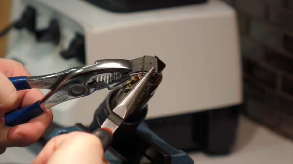
Or does it? As [Curious Marc] documents in the video below, a little heat and some finesse are all it takes, at least for some chips. The method is demonstrated by [Antoine Bercovici], a paleobotanist who sidelines as a collector of old chips. After removing chips from a PCB — he harvested these chips from an old PlayStation — he uses hot air to soften the epoxy, and then flexes the chip with a couple of pairs of pliers. It’s a bit brutal, but in most of the Sony chips he tried for the video, the epoxy broke cleanly over the die and formed a cleavage plane that allowed the die to be slipped out cleanly. The process is not unlike revealing fossils in sedimentary rocks, a process that he’s familiar with from his day job.
He does warn that certain manufacturers, like Motorola and National, use resins that tend to stick to the die more. It’s also clear that a hairdryer doesn’t deliver enough heat; when they switched to a hot air rework station, the success rate went way up.
The simplicity of this method should open the decapping hobby up to more people. Whether you just want to take pretty pictures or if reverse engineering is on your mind, put the white fuming nitric acid down and grab the heat gun instead.