Solder Bridges Aid Desoldering

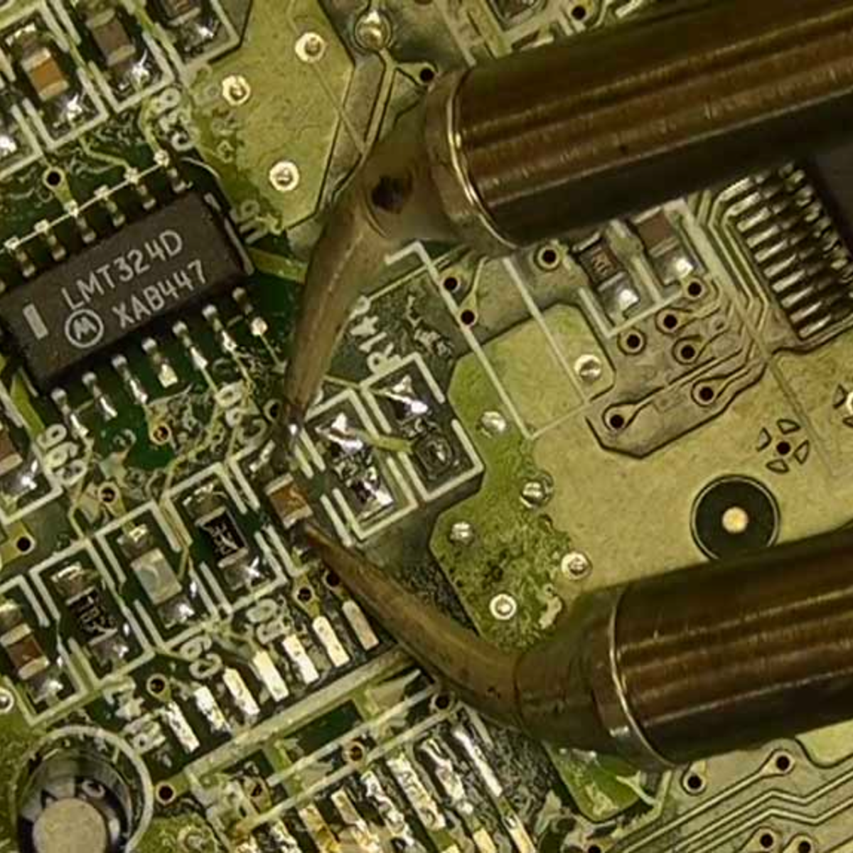
As our own Elliot Williams laid out, many people think that soldering is a key skill for electronics, but we don’t as often think about desoldering. Even if you are perfect in your technique, there’s always the chance you’ll put in a bad part or have a part fail later and it will need replacement. [Robert] has a short video showing his method for removing through-hole components and you can see it below.

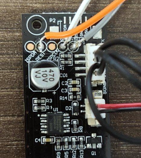
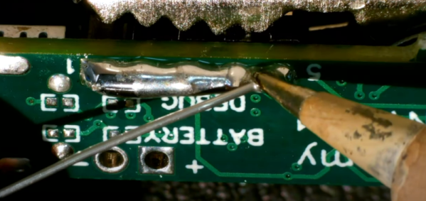
This isn’t the first time we’ve seen it, of course. In fact, it is very much like using hot air, although it doesn’t require hot air, just extra solder and a regular iron. Of course, if we knew that connector was bad, we’d have been tempted to cut each pin apart and remove them one at a time. Heating a joint and then slamming your hand on the bench can work wonders.

We always think desoldering pumps are a good idea, but the electric ones tend to be anemic. The ones with the springs are usually better, but still have limitations. In the end, we’ll stick with using hot air, but if all you have is an iron, this method is worth checking out. You might also be interested in the needle method.

Continue reading “Solder Bridges Aid Desoldering”

Monowheel Balancing Robot Can’t Turn (Yet)

Self-balancing robots have become a common hobby project, and they usually require two wheels to work. [James Bruton] has managed to single wheel balancing robot by adding gyroscopic stabilization.

[James] has done other self-balancing robots, like his Sonic robot, but recently started experimenting with gyroscopic stabilization. In that project, he proposed the idea of combining the two stabilization methods to create a monowheel robot, and he followed through on that idea. The wheel is powered by a brushless motor and is stabilized conventionally around the wheel’s axis. Side to side balancing is achieved using a phenomenon known as gyroscopic precession, by tilting a pair of heavy spinning wheels. This is not to be confused with reaction wheels, which use rotational inertia for control. It appears the actuating the gyroscopes also affects the front-to-back stabilization, so at the moment the robots won’t stay on one spot. [James] plans to implement a second observation controller in software to solve this.

Another challenge with this robot is that it cannot turn at the moment. The gyroscopes are not in the correct orientation to effect rotation around the vertical axis, and changing their orientation would cause other problems. A fan, which works like a helicopter’s tail rotor is one option, and a reaction wheel on top might also work. We’re partial to the reaction wheel idea. Having a different mechanical control mechanism for each axis would make it quite an interesting robot.

Continue reading “Monowheel Balancing Robot Can’t Turn (Yet)”

Walk The First 3D-Printed Bridge And Be Counted

Way back in 2018, we brought you news of a 3D-printed stainless steel pedestrian bridge being planned to span a Dutch canal in Amsterdam. Now it’s finally in place and open to the public — the Queen made it official and everything. MX3D printed it on their M1 Metal additive manufacturing machine that is essentially a group of robots welding layers of metal together using traditional welding wire and gas.

The partnership of companies involved originally planned to build this beautiful bridge in situ, but safety concerns and other issues prevented that and it was built in a factory instead. The bridge has been printed and ready since 2018, but a string of delays got in the way, including the fact that the canal’s walls had to be refurbished to accommodate it. Since it couldn’t be made on site, the bridge was taken there by boat and placed with a crane. After all this, the bridge is only permitted to be there for two years. Hopefully, they have the option to renew.

This feat of engineering spans 40 feet (12.2 meters) long and sits 20 feet (6.3 meters) wide. It’s equipped with sensors that measure structural stuff like strain, displacement, load, and rotation, and also has environmental sensors for air quality and temperature. All of this data is sent to the bridge’s digital twin, which is an exact replica in the form of a computer model. One of the goals is to teach the bridge how to count people. Be sure to check out our previous coverage for a couple of short videos about the bridge.

Avoid Awkward Video Conference Situations With PIR And Arduino

Working from home with regular video meetings has its challenges, especially if you add kids to the mix. To help avoid embarrassing situations, [Charitha Jayaweera] created Present!, a USB device to automatically turn of your camera and microphone if you suddenly need to leave your computer to maintain domestic order.

Present consists of just a PIR sensor and Arduino in a 3D printed enclosure to snap onto your monitor. When the PIR sensor no longer detects someone in range, it sends a notification over serial to a python script running on the PC to switch off the camera and microphone on Zoom (or another app). It can optionally turn these back on when you are seated again. The cheap HC-SR501 PIR module’s range can also be adjusted with a trimpot for your specific scenario. It should also be possible to shrink the device to the size of the PIR module, with a small custom PCB or one of the many tiny Arduino compatible dev boards.

For quick manual muting, check out the giant 3D printed mute button. Present was an entry into the Work from Home Challenge, part of the 2021 Hackaday Prize.

Learning To Desolder Gracefully

When you’re just learning to sketch, you use graphite. Why? It’s cheap, great at training you to recognize different shades, and most of all, it’s erasable. When you’re learning, you’re going to make mistakes, and un-making them is an important part of the game. Same goes for electronics, of course, so when you’re teaching someone to solder, don’t neglect teaching them to desolder.

I want these!

We could argue all day about the best ways of pressing the molten-metal undo button, but the truth is that it’s horses for courses. I’ve had really good luck with solder braid and maybe a little heat gun to pull up reluctant SOIC surface-mount chips, but nothing beats a solder sucker for clearing out a few through-holes. (I haven’t tried the questionable, but time-tested practice of blasting the joint with compressed air.)

For bulk part removal, all you really have to do is heat the board up, and there’s plenty of ways to do that, ranging from fancy to foolish. Low-temperature alloys help out in really tough cases. And for removing rows of pinheaders, it can help to add more solder along the row until it’s one molten blob, and then tap the PCB and watch the part — and hot liquid metal! — just drop out.

But the bigger point is that an important step in learning a new technique is learning to undo your mistakes. It makes it all a lot less intimidating when you know that you can just pull out the solder braid and call “do-over”. And don’t forget the flux.

ESP8266 Adds WiFi Logging To IKEA’s Air Quality Sensor

Introduced back in June, the IKEA VINDRIKTNING is a $12 USD sensor that uses colored LEDs to indicate the relative air quality in your home depending on how many particles it sucks up. Looking to improve on this simplistic interface, [Sören Beye] tacked an ESP8266 to the board so it can broadcast sensor readings out over MQTT.

Just three wires link the ESP8266 to the PCB.

While some of us would have been tempted to gut the VINDRIKTNING and attach its particle sensor directly to the ESP8266, the approach [Sören] has used is actually quite elegant. Rather than replacing IKEA’s electronics, the microcontroller is simply listening in on the UART communications between the sensor and the original controller. This not only preserves the stock functionality of the VINDRIKTNING, but simplifies the code as the ESP doesn’t need to do nearly as much.

All you need to do if you want to perform this modification is solder a couple wires to convenient test pads on the VINDRIKTNING board, then flash the firmware (or write your own version), and you’re good to go. There’s plenty of room inside the case for the ESP8266, though you may want to tape it down so it doesn’t impact air flow.

While not required, [Sören] also recommends making a small modification to the VINDRIKTNING which makes it a bit quieter. Apparently the 5 V fan inside the sensor is occasionally revved up by the original controller, rather than kept at a continuous level that you can mentally tune out. But by attaching the sensor’s fan to the ESP8266’s 3.3 V pin, it will run continuously at a lower speed.

We’ve seen custom firmware for IKEA products before, but this approach, which keeps the device’s functionality intact regardless of what’s been flashed to the secondary microcontroller, is particularly appealing for those of us who can’t seem to keep the gremlins out of our code.

[Thanks to nexgensri for the tip.]

How The Flipper Zero Hacker Multitool Gets Made And Tested

Flipper Zero is an open-source multitool for hackers, and [Pavel] recently shared details on what goes into the production and testing of these devices. Each unit contains four separate PCBs, and in high-volume production it is inevitable that some boards are faulty in some way. Not all faults are identical — some are not even obvious —  but they all must be dealt with before they end up in a finished product.

One of several custom test jigs for Flipper Zero. Faults in high volume production are inevitable, and detecting them early is best.

Designing a process to effectively detect and deal with faults is a serious undertaking, one the Flipper Zero team addressed by designing a separate test station for each of the separate PCBs, allowing detection of defects as early as possible. Each board gets fitted into a custom test jig, then is subjected to an automated barrage of tests to ensure everything is as expected before being given the green light. A final test station gives a check to completed assemblies, and every test is logged into a database.

It may seem tempting to skip testing the individual boards and instead just do a single comprehensive test on finished units, but when dealing with production errors, it’s important to detect issues as early in the workflow as possible. The later a problem is detected, the more difficult and expensive it is to address. The worst possible outcome is to put a defective unit into a customer’s hands, where a issue is found only after all of the time and cost of assembly and shipping has already been spent. Another reason to detect issues early is that some faults become more difficult to address the later they are discovered. For example, a dim LED or poor antenna performance is much harder to troubleshoot when detected in a completely assembled unit, because the fault could be anywhere.

[Pavel] provides plenty of pictures and details about the production of Flipper Zero, and it’s nice to see how the project is progressing since its hyper-successful crowdfunding campaign.