3D Printed Gesture-Controlled Robot Arm Is A Ton Of Tutorials

Ever wanted your own gesture-controlled robot arm? [EbenKouao]’s DIY Arduino Robot Arm project covers all the bases involved, but even if a robot arm isn’t your jam, his project has plenty to learn from. Every part is carefully explained, complete with source code and a list of required hardware. This approach to documenting a project is great because it not only makes it easy to replicate the results, but it makes it simple to remix, modify, and reuse separate pieces as a reference for other work.

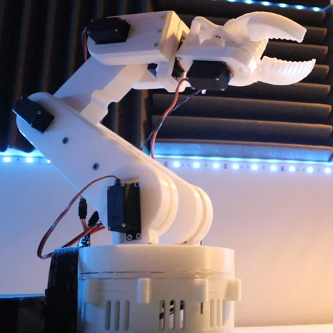
[EbenKouao] uses a 3D-printable robotic gripper, base, and arm design as the foundation of his build. Hobby servos and a single NEMA 17 stepper take care of the moving, and the wiring and motor driving is all carefully explained. Gesture control is done by wearing an articulated glove upon which is mounted flex sensors and MPU6050 accelerometers. These sensors detect the wearer’s movements and turn them into motion commands, which in turn get sent wirelessly from the glove to the robotic arm with HC-05 Bluetooth modules. We really dig [EbenKouao]’s idea of mounting the glove sensors to this slick 3D-printed articulated gauntlet frame, but using a regular glove would work, too. The latest version of the Arduino code can be found on the project’s GitHub repository.

Most of the parts can be 3D printed, how every part works together is carefully explained, and all of the hardware is easily sourced online, making this a very accessible project. Check out the full tutorial video and demonstration, embedded below.

Continue reading “3D Printed Gesture-Controlled Robot Arm Is A Ton Of Tutorials”

Scanner Snooping Uncovers Focus Farce

From his comments about the noisy image and limited controls, we’re going to go out on a limb and assume [Andrew Jeddeloh] isn’t a huge fan of using his Epson V550 for scanning film. But is it really irredeemable? That’s what he set out to determine in a recent series of posts on his blog, and from what we can tell, it’s not looking good for the old Epson.

The first post attempts to quantify the optical capabilities of the scanner by determining its modulation transfer function (MTF), point spread function (PSF), and comparing its horizontal and vertical resolution. As you might expect, the nuances of these measurements are a bit beyond the average user. The short version of his analysis is that the scanner’s slide frame does indeed seem to be holding objects at the proper “sweet spot” for this particular image sensor; meaning that contrary to the advice he’d seen online, there’s nothing to be gained by purchasing custom film or slide holders.

MTF versus height of film from bed.

While investigating the optical properties of the scanner, [Andrew] became curious about the automatic focus options offered by the VueScan software he was using. The images produced appeared to be identical regardless of what option he selected, and he began to suspect the feature wasn’t actually doing anything. To confirm his theory, he wrote a shim program that would sit between the proprietary VueScan program and the V550 driver and log all of the data passing between them.

After tweaking various options and comparing the captured data streams, [Andrew] determined that enabling automatic focus in VueScan doesn’t do anything. At least, not with his scanner. He did notice a few extra bytes getting sent to the driver depending on which focus options were selected, but the response from the scanner didn’t change. He thinks the program likely has some kind of generic framework for enabling these kind of features on supported hardware, and it’s just mistakenly showing the autofocus options for a scanner that doesn’t support it.

If there’s some film you want to digitize, but you’re saddled with a scanner like the V550, you could always do it with a camera instead. You could even put together a passable film scanner with LEGO.

The (Probably) Most Thoroughly Commented Linker Script For The SAM D21 MCU

Linker scripts are one of those things which nobody who does software development really wants to deal with, but like many things in life sometimes they are inevitable to make things work. Although one could keep pretending linker scripts do not exist and let IDEs handle such pesky details, some of us suffer from this unfortunate condition called ‘curiosity’ and just have to know. People like [Thea].

Recently, [Thea] wrote a blog post on exactly what the linker script generated by the Microchip IDE for a Cortex-M-based SAM D21 project does. The result is a nicely annotated overview of the file’s contents, accompanied by links to the Arm and GCC documentation as well as other references where appropriate. The entire linker script (.ld file) can be viewed on GitHub. With the SAM D21 being a popular choice for Arduino and Arduino-compatible board, this article is a good starting point to understanding what a linker script does and how it affects one’s project.

For other (Cortex-M) MCUs this linker script is also useful as a starting point. Especially knowing which sections are required and what changing them affects in the final (ELF) binary and the firmware that is ultimately written to the MCU. We recently covered linker scripts for Cortex-M as well, along with the concept of memory-mapped I/O.

Cura Plugin Offers Custom Support

[Chuck] likes the ability of Simplify3D to add support to parts of a model manually. However, not everyone wants to spend $150 for a slicer, so he’s shared how to install a plugin that allows you to do the same trick in Cura.

The plugin is “Cylindric Custom Support.” That doesn’t sound very exciting, but you get five choices of shapes you can create custom supports easily. There are also size and angle parameters you can use to customize the effect.

Continue reading “Cura Plugin Offers Custom Support”

Pen Plotter Draws Maps Directly On The Wall

For map-lovers like [Christopher Getschmann], poring over a quality map can be as satisfying as reading a good book. Good maps can be hard to come by, though, especially at a scale worth looking at, or worth using as adornment on a dull, lifeless wall. The solution is obvious: build a wall-mount CNC plotter to draw maps directly on the wall.

[Christopher] began his map quest by scraping world map data from a number of sources, including OpenStreetMap, Natural Earth, and GEBCO. This gave him data for coastlines, terrain, and bathymetry — enough for a map of the world large enough to fill a wall. Since the scale of the map would preclude the use of even a large-format inkjet printer, [Christopher] set about building a wall-covering pen-plotter to render the map. The CoreXY-style plotter is large, but still light enough to hang on the wall while it works, and to be repositioned to cover a larger area.

The plotter runs on steppers driven by ultra-quiet Trinamic TMC5160 drivers, so the plotter wouldn’t be a nuisance while it worked. The map was plotted on eight pieces of cardboard mounted directly to the wall, filling the 2- x 3-meter space almost entirely. Landmasses and elevation contours were plotted as continuous lines in black ink, while bathymetric data was rendered in blue ink as cross-hatching with variable spacing, to make deeper oceans darker blue.

We find [Christopher]’s map breathtaking, all the more so considering the work that went into making it. It would be interesting to find alternate uses for the plotter, which reminds us a little of a cross between a draw-bot and a Maslow vertical CNC router, now that it’s done with its cartographic duties.

Homebrew Relay Computer Looks Like It Could Be A Commercial Product

You may not have noticed, but we here at Hackaday really love our clicky stuff. Clicky mechanical keyboards, unnecessarily noisy flip-dot displays, and pretty much anything made with a lot of relays — they all grab our attention, in more ways than one. So it’s with no small surprise that we appear to have entirely missed perhaps the clickiest build of all: a fully operational 8-bit computer using nothing but relays.

What’s even more amazing about our failure to find and feature [Paul Law]’s excellent work is that he has been at it for the better part of a decade now. The first post on his very detailed and very well-crafted blog describing the build dates from 2013, when he was just testing LEDs in the arithmetic-logic unit (ALU). Since then, [Paul] has made incredible progress, building module after module, each containing a small portion of the computer’s functionality. The modules plug into card cages with backplanes to connect them, and the whole thing lives in an enclosure made from aluminum extrusion and glossy black panels for a truly sleek look. The computer is incredibly compact for something that uses 400+ DPDT relays to do its thinking.

In addition to the blog, [Paul] has a criminally undersubscribed YouTube channel with a quite recent series going over the computer in depth. We included the overall tour below, but you should really check out the rest of the videos to appreciate how much work went into this build. We’ve seen relay computers ranging in size from single-board to just plain ludicrous, but this one really takes the prize for fit and finish as well as functionality.

Continue reading “Homebrew Relay Computer Looks Like It Could Be A Commercial Product”

Remoticon Video: Learning The Basics Of Software-Defined Radio (SDR)

Have you dipped your toe into the SDR ocean? While hacker software-defined radio has been a hot topic for years now, it can be a little daunting to try it out for the first time. Here’s your change to get your legs under you with the SDR overview workshop presented by Josh Conway during the 2020 Hackaday Remoticon.

Josh’s presentation starts with a straightforward definition of SDR before moving to an overview of the hardware and software that’s out there. Hardware designs for radios can be quite simple to build, but they’ll be limited to a single protocol — for instance, an FM radio can’t listen in on 433 Mhz wireless doorbell. SDR breaks out of that by moving to a piece of radio hardware that can be reconfigured to work with protocols merely by making changes to the software that controls it. This makes the radio hardware more expensive, but also means you can listen (and sometimes transmit) to a wide range of devices like that wireless doorbell or automotive tire pressure sensors, but also radio-based infrastructure like airplane transponders and weather satellites.

This is the quickstart you want since it explains  a lot of topis at just the right depth. The hardware overview covers RTL-SDR, ADALM-PLUTO, HackRF, KerberosSDR, and BladeRF (which we just featured over the weekend used on the WiFi procotol). For software, Josh recaps GQRX, SDR#, SDRAngel, ShinySDR, Universal Radio Hacker, Inspectrum, SigDigger, RPITX, GnuRadio Companion, and REDHAWK. He also takes us through a wide swath of the antenna types that are out there before turning to questions from the workshop attendees.

If SDR is still absent in your toolbox, now’s a great time to give it another look. Once you’ve made it through the ‘hello world’ stage, there’s plenty to explore like those awesome RF Emissions testing tricks we as in another Remoticon talk.

Continue reading “Remoticon Video: Learning The Basics Of Software-Defined Radio (SDR)”