Magnetic Gearbox Design Improvements Are Toothless But Still Cool

Any project that contains something called a “flux modulator” instantly commands our attention. And while we’re pretty sure that [Retsetman] didn’t invent it after hitting his head on the toilet, this magnetic gearbox is still really cool.

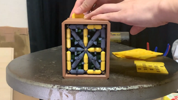
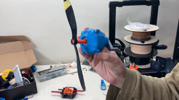
Where most gearboxes have, you know, gears, a magnetic gearbox works by coupling input and output shafts not with meshing teeth but via magnetic attraction. [Retsetman]’s version has three circular elements nested together on a common axis, and while not exactly a planetary gear in the traditional sense, he still uses planetary terminology to explain how it works. The inner sun gear is a rotor with four pairs of bar magnets on its outer circumference. An outer ring gear has ten pairs of magnets, making the ratio of “teeth” between the two gears 10:2. Between these two elements is the aforementioned flux modulator, roughly equivalent to the planet gears of a traditional gearbox, with twelve grub screws around its circumference. The screws serve to conduct magnetic flux between the magnets, dragging the rotating elements along for the ride.

This gearbox appears to be a refinement on [Retsetman]’s earlier design, and while he provides no build files that we can find, it shouldn’t be too hard to roll your own designs for the printed parts.

Continue reading “Magnetic Gearbox Design Improvements Are Toothless But Still Cool”

A schematic explaining the workings of the Commodore 64's joystick port

Bluetooth Interface Adds Rumble Feedback To Commodore 64 Games

Nothing says “1980s gaming” like a black joystick with a single red fire button. But if you prefer better ergonomics, you can connect modern gamepads to your retrocomputers thanks to a variety of modern-to-classic interface adapters. These typically support just the directional pad and one or two action buttons, leaving out modern features like motion control and haptic feedback.

That’s a bit of a shame, because we think it would be pretty cool to feel that shock in our hands whenever Pitfall Harry drowns in quicksand or Frogger gets hit by traffic. We’re therefore happy to report that [Ricardo Quesada] has decided to add rumble functionality to the Bluetooth-to-Joystick-port interface that he’s been working on. He demonstrates the feature on his Commodore 64 in the video embedded after the break.

Naturally, any software needs to be adapted to support haptic feedback, but a trickier problem turned out to be the hardware: joystick ports are input-only devices and therefore cannot send “enable rumble” signals to any connected gamepads. [Ricardo] found a clever way around this, using the analog inputs on the joystick port that were typically used for paddle-type controllers.

The analog-to-digital converter inside the computer works by applying a pulse signal to the analog port and measuring the time it takes to discharge a capacitor. The modern gamepad interface simply detects whether these pulses are present; they can be enabled or disabled through software by toggling the analog readout on the joystick port. This way, the joystick port can be used to send a single bit of information to any device connected to it.

[Ricardo] developed patches for Rambo: First Blood part II and Leman to enable rumble functionality. He describes the process in detail in his blog post, which should enable anyone who knows their way around 6502 machine code to add rumble support to their favorite games.

The adapter works with a variety of retro systems that use the Atari-style joystick interface, but if you’re an Apple II user, you might want to look at this Raspberry Pi-based project that interfaces with its nonstandard joystick interface. If you’re into wireless gaming in general, be sure to also check out our history of wireless game controllers.

Continue reading “Bluetooth Interface Adds Rumble Feedback To Commodore 64 Games”

I’ll See Your Seven-Segment Mechanical Display And Raise You To 16 Segments

Mechanical multi-segment displays have become quite a thing lately, and we couldn’t be more pleased about it. The degree of mechanical ingenuity needed to make these things not only work but look good while doing it never ceases to amaze us, especially as the number of segments increases. So we submit this over-the-top 16-segment mechanical display (Nitter) for your approval.

The original tweet by [Kango Suzuki] doesn’t have a lot of detail, especially if you can’t read Japanese, but we did a little digging and found the video shown below. It shows a lot more detail on how this mechanism works, as well as some of the challenges that cropped up while developing it. Everything is 3D printed, and flipping the state of each of the 16 segments is accomplished with a rack-and-pinion mechanism, with the pinions printed right into each two-sided cylindrical segment. The racks are connected to pushrods that hit a punch card inserted into a slot in the rear of the display. The card has holes corresponding to the pattern to be displayed; when it’s pushed home, the card activates a mechanism that slides all the racks that line up with holes and flips their segments.

This isn’t the first multi-segment mechanical masterpiece from [Kango Suzuki] that we’ve featured, of course. This wooden seven-segment display works with cams rather than punch cards, but you can clearly see the hoe the earlier mechanism developed into the current work. Both are great, and we’re looking forward to the next segment count escalation in the mechanical display wars.

Continue reading “I’ll See Your Seven-Segment Mechanical Display And Raise You To 16 Segments”

Mommy, Where Do Ideas Come From?

We wrote up an astounding old use of technology – François Willème’s 3D scanning and modeling apparatus from 1861, over 150 years ago. What’s amazing about this technique is that it used absolutely cutting-edge technology for the time, photography, and the essence of a technique still used today in laser-line 3D scanners, or maybe even more closely related to the “bullet time” effect.

This got me thinking of how Willème could have possibly come up with the idea of taking 24 simultaneous photographs, tracing the outline in wood, and then re-assembling them radially into a 3D model. And all of this in photography’s very infancy.

But Willème was already a sculptor, and had probably seen how he could use photos to replace still models in the studio, at least to solidify proportions. And he was probably also familiar with making cameos, where the profile was often illuminated from behind and carved, often by tracing shadows. From these two, you could certainly imagine his procedure, but there’s still an admirable spark of genius at work.

Could you have had that spark without the existence of photography? Not really. Tracing shadows in the round is impractical unless you can fix them. The existence of photography enabled this idea, and countless others, to come into existence.

That’s what I think is neat about technology, and the sharing of new technological ideas. Oftentimes they are fantastic in and of themselves, like photography indubitably was. But just as often, the new idea is a seed for more new ideas that radiate outward like ripples in a pond.

[Tom Stanton] Builds An Osprey

The V-22 Osprey is an aircraft like no other. The tiltrotor multirole military aircraft makes an impression wherever it goes; coincidentally, a flight of two of these beasts flew directly overhead yesterday and made a noise unlike anything we’ve ever heard before. It’s a complex aircraft that pushes the engineering envelope, so naturally [Tom Stanton] decided to build a flight-control accurate RC model of the Osprey for himself.

Sharp-eyed readers will no doubt note that [Tom] built an Osprey-like VTOL model recently to explore the basics of tiltrotor design. But his goal with this build is to go beyond the basics by replicating some of the control complexity of a full-scale Osprey, without breaking the bank. Instead of building or buying real swash plates to control the collective and cyclic pitch of the rotors, [Tom] used his “virtual swashplate” technique, which uses angled hinges and rapid changes in the angular momentum of the motors to achieve blade pitch control. The interesting part is that the same mechanism worked after adding a third blade to each rotor, to mimic the Osprey’s blades — we’d have thought this would throw the whole thing off balance. True, there were some resonance issues with the airframe, but [Tom] was able to overcome them and achieve something close to stable flight.

The video below is only the first part of his build series, but we suspect contains most of the interesting engineering bits. Still, we’re looking forward to seeing how the control mechanism evolves as the design process continues.

Continue reading “[Tom Stanton] Builds An Osprey”

A Rail Cart For The Space Conscious Passenger

For those who live in countries where there are plenty of abandoned railways, a popular way to explore them has been by means of home made rail carts. These are usually rudimentary rail trolleys with a small internal combustion engine, and a host of fascinating videos of them can be found online. Such a trolley has one disadvantage though — it’s not the most compact of devices. [Cato] has come up with a rail cart that’s extremely portable by replacing the engine with the guts of a pair of hoverboards.

The chassis of the machine is made from aluminium extrusion, and its deck from plywood. The wheels are the stock hoverboard wheels with flat flanges applied, which while they don’t have the ideal flange profile of a rail wheel are good enough to keep the thing on track. Finally to control the thing a rather stylish little 3D printed single-axis joystick serves as a combined throttle and brake.

Those of us who hail from places where abandoned railways have their track speedily ripped up can only gaze in envy and imagine speeding along the rails on one of these. The build starts with a warning never to use one of these on an active track, but should you wish to drive a real train there are plenty of places to do that.

A bike computer sits on a wooden background. The back of the bike computer has a 3D printed attachment with two white translucent zip ties running through the back.

Repairing A Bike GPS With 3D Printing

We love hacks that keep gadgets out of the trash heap, and [Brieuc du Maugouër] has us covered with this 3D printable replacement mount he designed for his bike GPS.

One of the most frustrating ways a gadget can fail is when a small, but critical part of the device fails. [du Maugouër] combined a 3D printed back and four M2x6mm screws to make a robust new mount to replace the broken OEM mount on his handlebar-mounted GPS. Slots for zip tie mounting are included in case the replacement mount breaks before yet another replacement can be printed. Apparently [du Maugouër] agrees with Chief O’Brien that “in a crunch, I wouldn’t like to be caught without a second backup.” [Youtube]

It’s exciting that we’re finally in a time when 3D printed replacement parts are living up to their potential. This would be a lot easier if more manufacturers posted 3D printed design files instead of getting them pulled from 3D file platforms, but makers will find a way regardless of OEM approval.

We’ve covered a lot of bike hacks over the years including DIY Bike Computers and GPS Trackers. Do you have a project that keeps something from becoming trash or might save the world another way? There’s still time to enter the Save the World Wildcard round of the Hackaday Prize (closes October 16th).