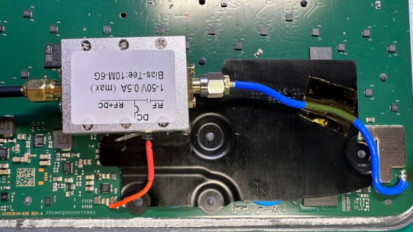
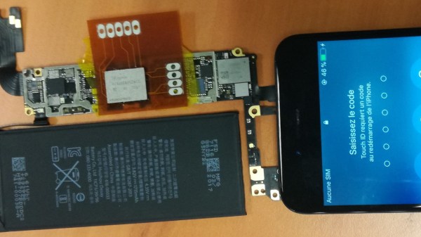
Two pictures of the mobo side by side, both with kapton tape covering everything other than the flash chip. On the left, the flash chip is populated, whereas on the right it's not

Enabling Intel AMT For BIOS-over-WiFi

Intel ME, AMT, SMT, V-Pro… All of these acronyms are kind of intimidating, all we know about them is that they are tied to remote control technologies rooted deep in Intel CPUs, way deeper than even operating systems go. Sometimes though, you want remote control for your own purposes, and that’s what [ABy] achieved. He’s got a HP ProDesk 600 G3 Mini, decided to put it into a hard to reach spot in his flat, somewhere you couldn’t easily fetch a monitor and a keyboard for any debugging needs. So, he started looking into some sort of remote access option in case he’d need to access the BIOS remotely, and went as far as it took to make it work. (Google Translate)

The features he needed are covered by Intel AMT — specifically, BIOS access over a WiFi connection. However, his mini PC only had SMT enabled from the factory, the cut-down version of AMT without features like wireless support. He figured out that BIOS dumping was the way, promptly did just that, found a suitable set of tools for his ME region version, and enabled AMT using Intel’s FIT (Flash Image Tool) software.

Now, dumping the image could be done from a running system fully through software, but apparently, flashing back requires an external programmer. He went with the classic CH341, did the 3.3 V voltmod that’s required to make it safe for flash chip use, and proceeded to spend a good amount of time making it work. Something about the process was screwy, likely the proprietary CH341 software. Comments under the article highlight that you should use flashrom for these tasks, and indeed, you should.

This article goes into a ton of detail when it comes to working with Intel BIOS images — whichever kind of setting you want to change, be it AMT support or some entirely different but just as tasty setting, you will be well served by this write-up. Comments do point out that you might want to upgrade the Intel ME version while at it, and for what it’s worth, you can look into disabling it too; we’ve shown you a multitude of reasons why you should, and a good few ways you could.

Diagram from the blog post, showing how GATT communication capture works

Hacking BLE To Liberate Your Exercise Equipment

It’s a story we’ve heard many times before: if you want to get your data from the Domyos EL500 elliptical trainer, you need to use a proprietary smartphone application that talks to the device over Bluetooth Low-Energy (BLE). To add insult to injury, the only way to the software will export your workout information is by producing a JPG image of a graph. This just won’t do, so [Juan Carlos Jiménez] gives us yet another extensive write-up, which provides an excellent introduction to practical BLE hacking.

He walks us through BLE GATT (Generic Attribute Profile), the most common way such devices work, different stages of the connection process, and the tools you can use for sniffing an active connection. Then [Juan] shows us a few captured messages, how to figure out packet types, and moves into the tastiest part — using an ESP32 to man-in-the-middle (MITM) the connection.

Continue reading “Hacking BLE To Liberate Your Exercise Equipment”

The Pi Pico replacement board in question, assembled, held diagonally in some type of holder

ProPico For Your Pro Pico Needs

Ever feel like the Pi Pico board could be doing way more given its footprint? Does it bother you that the RP2040’s ADC quality is even further decreased because of the noisy onboard switching regulator? Miffed about decisions like the MicroUSB socket, the 2MB flash, or lack of the reset button? [Dmytro] brings us an open-source Pi Pico design, sporting the same RP2040 and a fully compatible footprint, but adding a number of improvements to its surroundings.

There’s a good few additions, all of them hacker-friendly – [Dmytro] adds comfortably-spaced reset and boot buttons, a USB-C socket, a dedicated low-noise voltage reference for the ADC, one more LED, and an I2C EEPROM footprint socket that is compatible with FRAM chips. Everything worth preserving is preserved – the pinout stays the same, including the SWD connector, which now sports an extra RESET pin. The bottom side USB testpoints remain, with only the four testpoints changed for more useful signals. Last but not least, the switching regulator is replaced by the venerable 1117 – you lose the ability to power your Pico from two AAs, and the capacitor series resistor requirement isn’t great, but you can easily put one of the drop-in 1117 replacement regulators on there.

What’s great is that the design is fully open-source, with KiCad files available. Want to design your own Pi Pico footprint board, improve upon this one even further, or maybe make a more tailored one? Treat yourself to the GitHub repository! There’s also a pinout diagram and a KiCanvas schematic for all your tinkering needs. We’ve covered drop-in replacements for classic drawer-inhabiting parts like the Pi Zero, for the 7805 (twice!), the 6502 CPU, and even for the DE9 serial port connector. No matter the purpose, they’re always a joy to see.

The controller after the rebuild, looking just like the stock controller but with an external antenna attached

An Extensive Walkthrough On Building Your Own KSP Controller

Having a game-tailored controller is a level-up in more ways than one, letting you perform in-game actions quickly and intuitively, instead of trying to map your actions to a clunky combination of keyboard and mouse movements. [abzman] took the Pelco KBD300A, a DVR-intended camera controller panel with a joystick, reverse-engineered it, and then rebuilt it into a Kerbal Space Program controller. What’s more, he documented every detail along the way!

The write-up is so extensive, it’s four separate posts — all of them worth reading without a doubt. In the first post, he describes the original hardware, the process of reverse-engineering it, and a few tips for your own RE journeys. Next, he covers about making his own board, showing all the small decisions he’s had to make, with plenty of KiCad screenshots. If you are on the lookout for designing such a board, there’s plenty to learn!

The original hardware didn’t go down without a fight — the third post talks about taming the seven-segment displays, the onboard joystick, and fighting with the key matrix wired in exactly the way you wouldn’t want. In the end, he shows us how you could tie a controller easily into Kerbal Space Program.

One more piece of hardware liberated, one more win for the hacker world. Whether it’s a Macintosh SE, a classic ThinkPad, or even a generic rotary tool, these upgrades are always a joy to see. If you wanted to learn to do such an upgrade yourself, here’s us showing how you can pull this off with a classic Sony Vaio!

Jana showing the board in action, with a magnetic probe attached to it

Add The Analog Toolkit To Your…Toolkit

Analog acquisition tools are super helpful whenever you want to run an experiment, test out a theory, or improve upon your code, and you won’t realize how much you always needed one up until you’re facing a situation where it’s the only tool for the task. Well, here’s a design you might just want to add to your next PCB order — the STM32G4 Analog Toolkit from [Jana Marie].

The recommended STM32G431 is a wonderful tool for the task in particular. For a start, this board exposes nine 16-bit ADC inputs, with six of them capable of differential mode and three of them having the PGA (Programmable Gain Amplifier) feature. There’s also two 12-bit DAC pins, two timer outputs, three GPIOs, and UART with I2C for the dessert. As a bonus, it can work as a PD trigger, giving you higher-than-5V voltages out of USB-C for any experiments of yours.

The board requires only a few components, most of them easily solderable, with the STM32 in the TQFP32 package. The BOM is optimized, the GPIOs are used up to the max, with two spare GPIOs driving an RGB LED using a witty control scheme. There’s even a place to clip an alligator clip, in case that’s what your probing hardware wants! All in all, this is a carefully crafted design certainly worth having on hand.

Make sure to get a few of these made before you find yourself desperately needing one! That said, there’s always a backup option, the venerable ATtiny85.

render of a sample board produced with help of this plugin. it's pretty, has nice lighting and all!

From KiCad To Blender For A Stunning Render

We love Blender. It brings you 3D modeling, but not in a CAD way — instead, people commonly use it to create animations, movies, games, and even things like VR models. In short, Blender is about all things art and visual expression. Now, what if you want a breathtaking render of your KiCad board? Look no further than the pcb2blender tool from [Bobbe 30350n].

This isn’t the first time we’ve seen KiCad meet Blender. However, compared to the KiCad to Blender paths that people used previously, pcb2blender makes the import process as straightforward and as quick as humanly possible. Install a plugin for both tools, and simply transfer a .pcb3d file out of the KiCad plugin into the Blender plugin. Want to make the surfaces of your design look like they’re meant to look in real life? Use the free2ki plugin to apply materials to your 3D models. In fact, you should check out [30350n]’s Blender plugin collection and overall portfolio, it’s impressive.

There’s no shortage of Blender hacks – just this year we’ve covered a hacker straight up simulating an entire camera inside Blender for the purpose of making renders, and someone else showing how to use Stable Diffusion to texture 3D scenes at lightning speed. We even recently published a comprehensive tutorial on how to animate your robot in Blender ourselves! Want to give it a shot? Check out this quick and simple Red Bull can model design tutorial.

Thanks to [Aki] for sharing this with us!

The scope, with new knobs and stickers on it, front panel renovated

Explosion-Scarred Scope Gets Plastic Surgery Hackerspace Style

Some equipment comes with a backstory so impressive, you can’t help but treat it with reverence. For instance, this Hantek scope’s front panel and knobs have melted when a battery pack went up in flames right next to it. Then, it got donated to the CADR hackerspace, who have in turn given us a scope front panel refurbishing master class (translated, original), demonstrating just how well a typical hackerspace is prepared for performing plastic surgery like this.

All of the tools they used are commonplace hackerspace stuff, and if you ever wanted to learn about a workflow for repairs like these, their wiki post is a model example, described from start to end. They show how they could use a lasercutter to iterate through figuring out mechanical dimensions of the labels, cutting the silhouette out of cardboard as they tweaked the offsets. Then, they designed and printed out the new front panel stickers, putting them through a generic laminator to make them last. An FDM printer helped with encoder and button knob test fits, with the final version knobs made using a resin printer.

Everything is open-source – FreeCAD knob designs, SVG stickers, and their CorelDraw sources are linked in the post. With the open-source nature, there’s plenty of room to improvement – for instance, you can easily put these SVGs through KiCad and then adorn your scope with panels made out of PCBs! With this visual overhaul, the Hantek DSO5102P in question has gained a whole lot more character. It’s a comprehensive build, and it’s just one of the many ways you can compensate for a damaged or missing shell – check out our comprehensive DIY shell guide to learn more, and when you get to designing the front panel, we’ve highlighted a few lessons on that too.