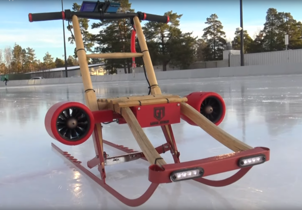
Street sledding, a popular pastime in Norway, is an activity that is slowly dwindling in popularity, at least as far as [Justin] aka [Garage Avenger] has noticed. It used to be a fun way of getting around frozen lakes and roads during winter, and while some still have their sleds [Justin] wanted to see if there was a way to revitalize one of these sleds for the modern era. He’s equipped this one with powerful electric turbines than can quickly push the sled and a few passengers around the ice.
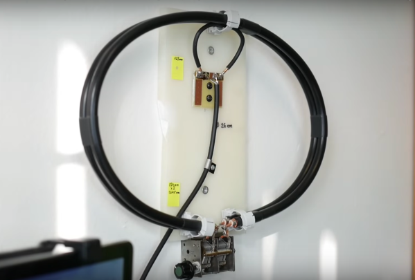
Since this particular sled is sized for child-sized passengers, fuel-burning jet engines have been omitted and replaced with electric motors that can spin their turbine blades at an impressive 80,000 rpm. The antique sled first needed to be refurbished, including removing the rust from the runners and reconditioning the wood. With a sturdy base ready to go, the sled gets a set of 3D printed cowlings for the turbines, a thumb throttle on the upgraded handlebars, and a big battery with an Arduino to bring it all together.
With everything assembled and a sheet of ice to try it out on, the powerful sled easily gets its passengers up to the 20-30 kph range depending on passenger weight and size. There’s a brake built on an old ice skate for emergency stops, and the sled was a huge hit for everyone at the skating pond. There are plenty of other ways to spruce up old sleds, too, like this one which adds a suspension for rocketing down unplowed roads.