Magnetic jack version of the bit-bang ethernet peripheral for Raspberry Pi Pico

Bit-Banging Bidirectional Ethernet On A Pi Pico

These days, even really cheap microcontroller boards have options that will give you Ethernet or WiFi access. But what if you have a Raspberry Pi Pico board and you really want to MacGyver yourself a network connection? You could do worse than check out this project by [holysnippet] that gives you a bit-banged bidirectional Ethernet port using only scrap passive components and software.

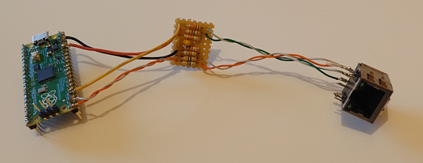
This project is similar to one we shared back in August by [kingyo], but differs in that what [holysnippet] has achieved is a fully-functional (albeit only around 7 Mbps) Ethernet port, rather than a simple UDP transmit device. The Ethernet connection itself is handled by the lwip stack. Connection to the RJ45 socket can be made from any of the Pi Pico pins, provided TX_NEG is followed directly by TX_POS, but the really hacky part is in the hardware.

schematic of Pi Pico bit-banged ethernet peripheral
Schematic showing the empirically-determined passive component values required.

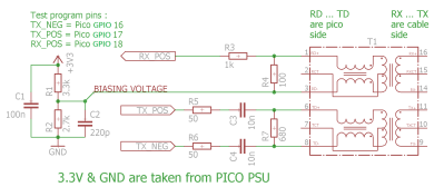
Rather than developing hardware that would protect the Pico, this design admits that it “shamefully relies on the Pico’s input protection devices” to limit the Ethernet voltages to 3.3 V.

You’ll need an isolation transformer from some old Ethernet-enabled gear (either standalone or as part of a magnetic jack), but then it’s only resistors and capacitors from there. There are warnings not to connect this to PoE networks for obvious reasons, and the component layout needs to keep in mind the ~20 MHz frequencies involved, but to get this working at all feels like quite a feat.

Normally, there’d be no reason to go to these lengths, but it’s always educational to see if it can be done and, with the current component shortages, this is another trick to keep up your sleeve for emergencies!

Putting ports where they shouldn’t belong is not a new idea, of course.  Back in the day we even shared an inadvisable ATTINY implementation of bit-banged Ethernet with no protection at all.

Thanks to [biemster] for the tip-off

IRL minesweeper render showing game on top of a campaign map

Meat-Space Minesweeper Game Hits The Mark

Hackers of a certain age will remember that before the Internet was available to distract us from our work, we had to find our own fun. Luckily, Windows was there to come to our aid, in the shape of “Minesweeper” – a classic of the age that involved figuring out/occasionally just guessing where a selection of mines had been hidden on a grid of squares via numerical clues to their proximity. For those missing such simple times, [Martin] has brought the game into physical space with his 3D-printed travel-game version.

GIF showing how to play IRL minesweeper game

A number of pre-determined game fields can be inserted (by a friend… or enemy, we presume!) and covered by tiles, which the mine-clearing player can then remove with their plastic shovel to reveal the clues. The aim of the game is to avoid uncovering a bomb, and to place flags where the bombs are hiding.

Aficionados of the game may remember that a little guessing was often inevitable, which sometimes ended in disaster. On the computer version, this merely entailed clicking the Smiley Face button for a new game, but in this case would require a new sheet to be inserted. Blank sheet templates are included for producing your own fiendish bomb-sites, and all the pieces pack away neatly into a handy clam-shell design that would be ideal for long car journeys when the data package on the kids’ tablets has run out.

We wonder what other classic games may lend themselves to a travel remake and look forward to the first 3D-printed travel set of Doom with anticipation!

If you’re above solving your own Minesweeper games, then you can learn how to write a solver in Java here. Continue reading “Meat-Space Minesweeper Game Hits The Mark”

The Fastest Fourier Transform In The West

An interesting aspect of time-varying waveforms is that by using a trick called a Fourier Transform (FT), they can be represented as the sum of their underlying frequencies. This mathematical insight is extremely helpful when processing signals digitally, and allows a simpler way to implement frequency-dependent filtration in a digital system. [klafyvel] needed this capability for a project, so started researching the best method that would fit into an Arduino Uno. In an effort to understand exactly what was going on they have significantly improved on the code size, execution time and accuracy of the previous crown-wearer.

A complete real-time Fourier Transform is a resource-heavy operation that needs more than an Arduino Uno can offer, so faster approximations have been developed over the years that exchange absolute precision for speed and size. These are known as Fast Fourier Transforms (FFTs). [klafyvel] set upon diving deep into the mathematics involved, as well as some low-level programming techniques to figure out if the trade-offs offered in the existing solutions had been optimized. The results are impressive.

Fastest FFT code benchmarking results in ms
Benchmarking results showing speed of implementation versus the competition (ApproxFFT)

Not content with producing one new award-winning algorithm, what is documented on the blog is a masterclass in really understanding a problem and there are no less than four algorithms to choose from depending on how you rank the importance of execution speed, accuracy, code size or array size.

Along the way, we are treated to some great diversions into how to approximate floats by their exponents (French text), how to control, program and gather data from an Arduino using Julia, how to massively improve the speed of the code by using trigonometric identities and how to deal with overflows when the variables get too large. There is a lot to digest in here, but the explanations are very clear and peppered with code snippets to make it easier and if you have the time to read through, you’re sure to learn a lot!  The code is on GitHub here.

If you’re interested in FFTs, we’ve seen them before around these parts. Fill your boots with this link of tagged projects.

Surface Mount Breathing Light PCB, using LM358 op-amp

Surface-Mount Light Breathes Life Into Your Project

If you’ve ever seen those gadgets with the “breathing light” LEDs on them and wondered how to do it, then [DIY GUY Chris] can show you how to design your own surface-mount version, using only analogue electronics.

Simulation trace showing the LED breathing light circuit operating. Traces for voltage and current are shown over a few seconds
The LED current tracks up and down in an approximately triangular-wave pattern

The circuit itself is built around a slow triangular-wave oscillator, that ramps the current up and down in the LEDs to make it look as if the lights are breathing in and out. The overall effect is rather pleasing, and the oscillation speed can be adjusted using the on-board potentiometer.

This project is actually an update to a previous version that used through-hole components (also shown in the video below), and goes to show that revisiting completed projects can give them a new lease of life. It also shows how easy it has become to design and order custom circuit boards these days. It’s not so long ago that a project like this would have been either made on stripboard or etched from copper-plated FR4 in a bubbling tank of acid!

If you have revisited an old project that you’re proud of and would like to show others, why not drop us a message on our tips line?

We have covered some other options for breathing LEDs in the past, such as this digital logic version, and this Arduino library that has a host of other effects to choose from, too. Continue reading “Surface-Mount Light Breathes Life Into Your Project”

IR Remote tester in use, showing a remote control lighting up an LED and screenshots of the Arduino serial terminal

IR Remote Tester Helps You Crack The Code

Even though some devices now use WiFi and Bluetooth, so much of our home entertainment equipment still relies on its own proprietary infrared remote control. By and large (when you can find them) they work fine, but what happens when they stop working?  First port of call is to change the batteries, of course, but once you’ve tried that what do you do next? [Hulk] has your back with this simple but effective IR Remote Tester / Decoder.

IR remote tester schematic showing arduino, receiver, LED and resistor
How to connect the TSOP4838 to an Arduino to read the transmitted codes

By using a cheap integrated IR receiver/decoder device (the venerable TSOP4838), most of the hard work is done for you! For a quick visual check that your remote is sending codes, it can easily drive a visible LED with just a resistor for a current-limit, and a capacitor to make the flickering easier to see.

For an encore, [Hulk] shows how to connect this up to an Arduino and how to use the “IRremote” library to see the actual data being transmitted when the buttons are pressed.

It’s not much of a leap to imagine what else you might be able to do with this information once you’ve received it – controlling your own projects, cloning the IR remote codes, automating remote control sequences etc..

It’s a great way to make the invisible visible and add some helpful debug information into the mix.

We recently covered a more complex IR cloner, and if you need  to put together a truly universal remote control, then this project may be just what you need.

Continue reading “IR Remote Tester Helps You Crack The Code”

"The Great Resistor" color code illumination project

The Great Resistor Embiggens The Smallest Value

With surface-mount components quickly becoming the norm, even for homebrew hardware, the resistor color-code can sometimes feel a bit old-hat. However, anybody who has ever tried to identify a random through-hole resistor from a pile of assorted values will know that it’s still a handy skill to have up your sleeve. With this in mind, [j] decided to super-size the color-code with “The Great Resistor”.

Resistor color code from Wikipedia with white background
How the resistor color-code bands work

At the heart of the project is an Arduino Nano clone and a potential divider that measures the resistance of the test resistor against a known fixed value. Using the 16-bit ADC, the range of measurable values is theoretically 0 Ω to 15 MΩ, but there are some remaining issues with electrical noise that currently limit the practical range to between 100 Ω and 2 MΩ.

[j] is measuring the supply voltage to help counteract the noise, but intends to move to an oversampling/averaging method to improve the results in the next iteration.

The measured value is shown on the OLED display at the front, and in resistor color-code on an enormous symbolic resistor lit by WS2812 RGB LEDs behind.

Inside view of the great resistor showing WS2812 LEDs and baffle plates
Inside The Great Resistor, the LEDs and baffle plates make the magic work

Precision aside, the project looks very impressive and we like the way the giant resistor has been constructed. It would look great at a science show or a demonstration. We’re sure that the noise issues can be ironed out, and we’d encourage any readers with experience in this area to offer [j] some tips in the comments below. There’s a video after the break of The Great Resistor being put through its paces!

If you want to know more about the history of the resistor color code bands, then we have you covered.  Alternatively, how about reading the color code directly with computer vision?

Continue reading “The Great Resistor Embiggens The Smallest Value”

PySpectrometer version 2, showing mini spectroscope, 4 inch display and hand for scale

Pi-based Spectrometer Gets An Upgrade

Here at Hackaday, we love to see projects re-visited and updated after we’ve covered them on the site. It’s always exciting to see what the creators come up with next, and this Pi-Based Spectrometer project is a great example of that.

[LesWright] found himself with a problem when the new version of Raspberry Pi operating system was released (Bullseye), and it broke some functionality on his original software. Rather than just fix the issues, [Les] chose to rewrite the software more dramatically and has ended up with a much more capable spectrometer that is able to match professional devices costing many times more.

Screenshot of Waterfall Display for PySpectrometer 2

By using multi-wavelength calibration and polynomial regression data, the new version is much more accurate and can now resolve wavelengths down to +/- 1nm.

The whole project is now written in OpenCV, and there’s a nifty new waterfall spectrum display, that will show changes in measured spectra over time.

A low-cost benchtop spectroscope is coupled to a RaspberryPi Camera via a CCTV zoom lens and the whole setup is mounted to a small block of aluminium for thermal and mechanical stability. The spectroscope is pointed at a fluorescent lamp and the user is guided through a calibration routine to tune the software to the hardware.

We’re impressed with the precision [Les] has achieved with his builds, and the write-up is sufficiently detailed to allow others to follow in his footsteps. We’d love to see if readers build one themselves, and what they use them for!

If you want to read up on the original build, you can find our article here. We’ve covered several spectrometry projects in the past, including this Gamma-Ray Spectrometer and this one based around an STM32 Nucleo board. Continue reading “Pi-based Spectrometer Gets An Upgrade”