Simple MicroPython Game Is A 30 Minute Game Dev Course

Sometimes, it’s really useful to watch a project’s parts come together one piece at a time in order to get a complete understanding and mental picture of the whole, and we found that to be the case with this simple, retro-inspired sample game from [ezContents]. (Video, embedded below.) The code is on GitHub but if you’re at all interested in what goes on behind the scenes in a game like that, don’t miss the video.

In the video, each game element and function is illustrated, showing exactly what gets done and why. This part is collision detection (click to enlarge.)

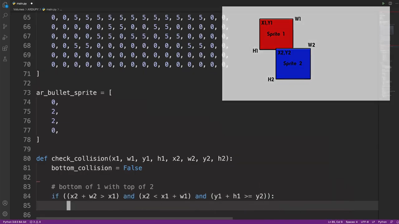
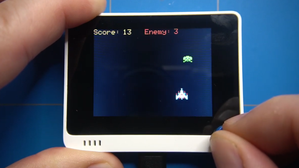
These sprite-based games are mostly about moving a small graphical object (a sprite) around a screen in response to user input, and managing what happens when collisions are detected between the player’s sprite and other sprites like enemies, projectiles, and so forth. The development process is wonderfully documented and demonstrated in a video, as each separate part of functionality gets built and explained one piece at a time.

The simple game is made using ArduPy (which is MicroPython combined with Arduino APIs) using Seeed Studios’ Wio Terminal, a small microcontroller development board with integrated screen, sensors, and button inputs including a little directional clicker that [ezContents] uses as a joystick.

The video of the whole process is embedded below; give it a watch and you’ll maybe come away with inspiration, but you’ll definitely have a much better understanding of how these types of games are developed, even if you’re not using the same hardware or development environment.

Continue reading “Simple MicroPython Game Is A 30 Minute Game Dev Course”

Iridescent Rainbow Chocolate, Just Add Diffraction Grating!

Chocolate plus diffraction grating equals rainbow chocolate

Here’s a great picture from [Jelly & Marshmallows] that shows off the wild effects of melted chocolate poured onto a diffraction grating. A diffraction grating is a kind of optical component whose micro-features act to disperse and scatter light. Diffraction gratings are available as thin plastic film with one side that is chock full of microscopic ridges, and the way light interacts with these ridges results in an iridescent, rainbow effect not unlike that seen on a CD or laserdisc.

It turns out that these micro-ridges can act as a mold, and pouring chocolate over a diffraction grating yields holo-chocolate. These photos from [Jelly & Marshmallows] show this effect off very nicely, but as cool as it is, we do notice that some of the letters seem a wee bit hit-or-miss in how well they picked up the diffraction grating pattern.

Fortunately, we know just what to suggest to take things to the next level. If you want to know more about how exactly this effect can be reliably accomplished, you’ll want to check out our earlier coverage of such delicious optics, which goes into all the nitty-gritty detail one could ever want about getting the best results with either melted sugar, or dark chocolate.

Omnibot From The 80s Gets LED Matrix Eyes, Camera

[Ramin assadollahi] has been busy rebuilding and improving an Omnibot 5402, and the last piece of hardware he wanted to upgrade was some LED matrix eyes and a high quality Raspberry Pi camera for computer vision. An Omnibot was something most technical-minded youngsters remember drooling over in the 80s, and when [ramin] bought a couple of used units online, he went straight to the workbench to give the vintage machines some upgrades. After all, the Omnibot 5402 was pretty remarkable for its time, but is capable of much more with some modern hardware. One area that needed improvement was the eyes.

The eyes on the original Omnibot could light up, but that’s about all they were capable of. The first upgrade was installing two 8×8 LED matrix displays to form what [ramin] calls Minimal Expressive Eyes (MEE), powered by a Raspberry Pi. With the help of a 3D-printed adapter and some clever layout, the LED matrix displays fit behind the eye plate, maintaining the original look while opening loads of new output possibilities.

Adding a high quality Raspberry Pi camera with wide-angle lens was a bit more challenging and required and extra long camera ribbon connector, but with the lens nestled just below the eyes, the camera has a good view and isn’t particularly noticeable when the eyes are lit up. Having already upgraded the rest of the hardware, all that remains now is software work and we can’t wait to see the results.

Two short videos of the hardware are embedded below, be sure to give them a peek. And when you’re ready for more 80s-robot-upgrading-action, check out the Hero Jr.

Continue reading “Omnibot From The 80s Gets LED Matrix Eyes, Camera”

Retro ISA Card Means Old, Slow Computers No Longer Need Old, Heavy Monitors

One thing about vintage computers is that they depend greatly on whether or not one can plug a compatible monitor into them. That’s what’s behind [Tube Time]’s Graphics Gremlin, a modern-design retro ISA video card that uses an FPGA to act just like a vintage MDA or CGA video card on the input end, but provides a VGA port for more modern display output options. (Actually, there is also an RGBI connector and a composite video out, but the VGA is probably the most broadly useful.)

Handy silkscreen labels make everything crystal clear. Click to enlarge.

Why bother making a new device to emulate an old ISA video card when actual vintage video cards are still plentiful? Because availability of the old cards isn’t the bottleneck. The trouble is that MDA or CGA monitors just aren’t as easy to come across as they once were, and irreplaceable vintage monitors that do still exist risk getting smashed during shipping. Luckily, VGA monitors (or at least converters that accept VGA input) are far more plentiful.

The board’s design files and assembly notes are all on the project’s GitHub repository along with plenty of thoughtful detail about both assembly and troubleshooting, and the Verilog code has its own document. The Graphics Gremlin is still under development, but you can also watch for the latest on [Tube Time]’s Twitter feed.

Thanks to [NoxiousPluK] for the tip!

Soil Moisture Sensors, How Do They Work?

In a way, the magic of a soil moisture sensor’s functionality boils down to a simple RC circuit. But of course, in practice there is a bit more to it than that. [rbaron] explains exactly how capacitive soil moisture sensors work simply, clearly, and concisely. He also shows, with a short video, exactly how their output changes in response to their environment, and explains how it informed his own sensor design.

At its heart, a moisture sensor measures how quickly (or slowly) a capacitor charges through a resistor, but in these sensors the capacitor is not a literal component, but is formed by two PCB traces that are near one another. Their capacitance — and therefore their charging rate — changes in response to how much water is around them. By measuring this effect on a probe sunk into dirt, the sensor can therefore indirectly measure the amount of water in the soil.

This ties into his own work on b-parasite: an open-source, all-in-one wireless soil moisture sensor (which was also a runner-up in our Earth Day contest) that broadcasts over BLE and even includes temperature readings. One thing to be mindful of if you are making your own PCBs or ordering them from a fab house is that passing current through metal in a moist environment is a recipe for oxidation, so it’s important not to expose bare traces to wet soil. A good coated PCB should avoid this problem, but one alternative we have seen proposed is to use graphite rods in place of metal.

3D-Printed Desiccant Container Exploits Infill

Desiccant is common in 3D printing because the drier plastic filament is, the better it prints. Beads of silica gel are great for controlling humidity, but finding a porous container for them that is a convenient size is a little harder. 3D printing is a generally useful solution for custom containers, but suffers from a slight drawback in this case: printing dense grills or hole patterns is not very efficient for filament-based printers. Dense hole patterns means lots of stopping and starting for the extruder, which means a lot of filament retractions and longer print times in general.

The green model is used as a modifier to the orange container (of which only the corners are left visible here)

[The_Redcoat]’s solution to this is to avoid hole patterns or grills altogether, and instead print large wall sections of the container as infill-only, with no perimeter layers at all. The exposed infill pattern is dense enough to prevent small beads of desiccant from falling through, while allowing ample airflow at the same time. The big advantage here is that infill patterns are also quite efficient for the printer to lay down. Instead of the loads of stops and starts and retractions needed to print a network of holes, infill patterns are mostly extruded in layers of unbroken lines. This translates to faster print speeds and an overall more reliable outcome, even on printers that might not be as well tuned or calibrated as they could be.

To get this result, [The_Redcoat] modeled a normal, flat-walled container then used OpenSCAD to create a stack of segments to use as a modifier in PrusaSlicer. The container is printed as normal, except where it intersects with the modifier, in which case those areas get printed with infill only and no walls. The result is what you see here: enough airflow for the desiccant to do its job, while not allowing any of the beads to escape. It’s a clever use of both a high infill as well as the ability to use a 3D model as a slicing modifier.

There’s also another approach to avoiding having to print a dense pattern of holes, though it is for light-duty applications only: embedding a material like tulle into a 3D print, for example, can make a pretty great fan filter.

Commodore 64 Emulator In VR Delivers A Full 80s Experience

The simulated color CRT monitor looks surprisingly convincing in VR.

One way to play with vintage hardware without owning the hardware is to use an emulator, but [omni_shaNker] announced taking it to the next level by using VR to deliver a complete Commodore 64 system, in its full glory, complete with a native 80s habitat playset! This is a pretty interesting angle for simulating vintage hardware, especially since the emulator is paired with what looks like a pretty convincing CRT monitor effect in VR, not to mention a virtual 5.25″ floppy drive that makes compellingly authentic sounds.

The project is hosted on GitHub and supports a variety of VR hardware, but for owners of Oculus headsets, the application is also available on SideQuest for maximum convenience. SideQuest is essentially an off-the-books app store for managing software that is neither approved nor distributed by Facebook. Oculus is owned by Facebook, and Facebook is keen to keep a tight grip on their hardware.

As functional as the application is, there are still improvements and optimizations to be made. To address this, [omni_shaNker] put out a call for beta testers on Reddit, so if that’s up your alley be sure to get in touch. A video demonstration and overview that is chock-full of technical details is also embedded below; be sure to give it a watch to see what the project is all about.

Continue reading “Commodore 64 Emulator In VR Delivers A Full 80s Experience”