After going through all the trouble of printing a part in resin, discovering it feels sticky or tacky to the touch is pretty unwelcome. Giving the model some extra ultraviolet (UV) curing seems like it should fix the problem, but it probably does not. So, what can be done?
The best thing to do with a sticky print is to immediately re-wash it in clean isopropyl alcohol (IPA) before the UV present in ambient light cures stray resin. If the part remains sticky after it is dry, more aggressive steps can be taken.
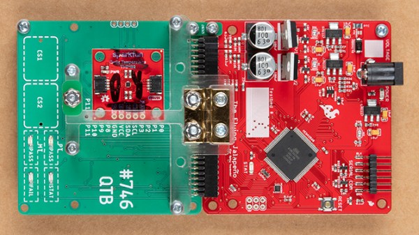
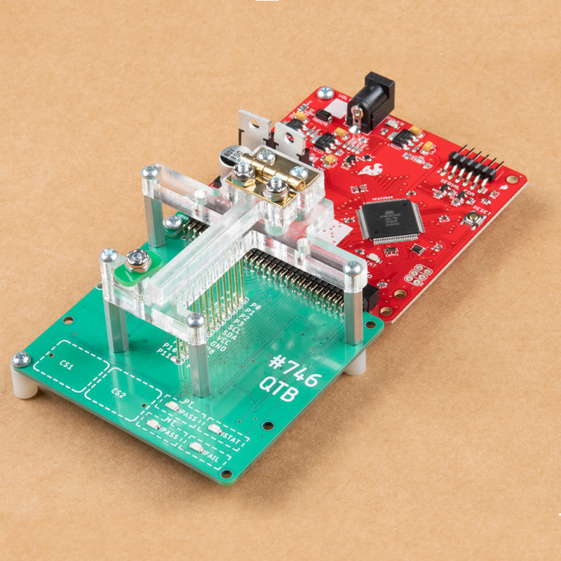
Test and programming fixtures are great time-savers for anyone who needs to deal with more than a handful of PCBs. Instead of plugging in connectors (or awkwardly holding probe tips or wires) to program some firmware or run tests, one simply pops a PCB into a custom fixture with one hand, and sips a margarita with the other while a program decides whether everything is as it should be. Test fixtures tend to be custom-made for specific board layouts, meaning one tester is needed per board or device type, but this work is easily justified by the huge time savings they offer.
An inserted PCB sits atop the thick acrylic piece, with pogo pins making contact from below. Generous space on the left and right make sure there is clearance for any mounted components. Visible near the bottom of the green board are output LEDs, and two touch-sensitive pads.
The test unit looks like pretty familiar stuff at first glance: some hardware responsible for running the test program, laser-cut acrylic jig to hold a test PCB in a consistent position, spring-loaded pogo pins to make temporary electrical connections, and LEDs to clearly indicate PASS and FAIL states. The clever part is the way the fixture is designed to accommodate multiple board designs, and how it uses several 74LVC4066 quad bilateral switch ICs to take care of switching which pogo pins are connected and to where.
As mentioned, to be compatible with multiple boards there must be common design elements to exploit. In Sparkfun’s case, the through-hole connections on their breakout boards are all in a row with standard 0.1″ spacing. By using the aforementioned pogo pins and 4066 ICs, different pinouts can be accommodated and multiple board types can be used without any need to swap to different test hardware.
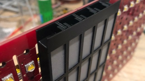
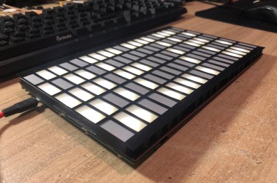
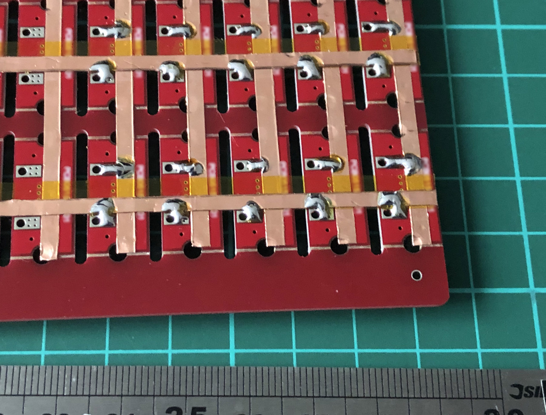
It all started when [Damien Walsh] got his hands on some surplus LED boards. Each panel contained 100 mini-PCBs hosting a single bright LED that were meant to be to be snapped apart as needed. [Damien] had a much better idea: leave them in their 20×5 array and design a driver allowing each LED to be controlled over WiFi. He was successful (a brief demo video is embedded down below after the break) and had a few interesting tips to share about the process of making it from scratch.
The first hurdle he ran into was something most of us can relate to; it’s difficult to research something when one doesn’t know the correct terms. In [Damien]’s case, his searches led him to a cornucopia of LED drivers intended to be used for room lighting or backlights. These devices make a large array of smaller LEDs act like a single larger light source, but he wanted to be able to individually address each LED.
Eventually he came across the IS32FL3738 6×8 Dot Matrix LED Driver IC from ISSI which hit all the right bases. Three of these would be enough to control the 100-LED panel; it offered I2C control and even had the ability to synchronize the PWM of the LEDs across multiple chips, so there would be no mismatched flicker between LEDs on different drivers. As for micontroller and WiFi connectivity, we all have our favorites and [Damien] is a big fan of Espressif’s ESP32 series, and used the ESP32-WROOM to head it all up.
LED pads bridged to copper tape, with Kapton (polyimide) tape insulating any crossovers.
The other issue that needed attention was wiring. Each of the LEDs is on its own little PCB with handy exposed soldering pads, but soldering up 100 LEDs is the kind of job where a little planning goes a long way. [Damien] settled on a clever system of using strips of copper tape, insulated by Kapton (a super handy material with a sadly tragic history.) One tip [Damien] has for soldering to copper tape: make sure to have a fume extractor fan running because it’s a much smokier process than soldering to wires.
A 3D-printed baffle using tracing paper to diffuse the light rounds out the device, yielding a 20 x 5 matrix of individually-controlled rectangles that light up smoothly and evenly. The end result looks fantastic, and you can see it in action in the short video embedded below.
Making your own handheld games is made much easier with [David Johnson-Davies’] simple sprite routines for the Adafruit PyBadge and PyGamer boards. Sprites can be thought of as small, fixed-size graphical objects that are drawn, erased, moved, and checked for collision with other screen elements.
xorSprite() plots an 8×8 sprite, moveSprite() moves a given sprite by one pixel without any flicker, and hitSprite() checks a sprite for collision with any screen elements in a given color. That is all it takes to implement a simple game, and [David] makes them easy to use, even providing a demo program in the form of the rolling ball maze shown here.
These routines work out-of-the-box with the PyBadge and PyGamer, but should be easy to adapt to any TFT display based on the ST7735 controller. The PyGamer is the board shown here, but you can see the PyBadge as it was used to create an MQTT-enabled conference badge.
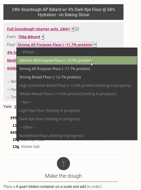
More people are making sourdough at home than ever before, and while it may not take a lot of effort to find a decent recipe, it’s quite another thing to try using recipes to figure out how and why bread actually works. Thankfully, [Makefast Workshop] has turned copious research and hundreds of trials into a dynamic sourdough (and semi-sourdough) bread recipe chock-full of of drop-down options to customize not just ingredients, but baking methods and other recipe elements as well. Want to adjust quantities or loaf styles? Play with hydration or flour type? It’s all right there, and they even have quick-set options for their personal favorites.
In order to do all this, [Makefast Workshop] needed to understand bread at a deeper level than is usually called for. During research, they observed that the format of recipes was often an obstacle to understanding how good bread actually gets made. The reason for this is simple: recipes are presented as standalone documents describing a fixed process; a set of specific steps that, when followed, yield a particular result. What they do not normally do is describe the interplay and balance between ingredients and processes, which makes it difficult to understand how and why exactly the recipe produces what it does. Without that knowledge, it’s impossible to know what elements can be adjusted, and how. The dynamic recipe changes all that.
[Makefast Workshop] performed hundreds of tests, dialing in parameters one by one, to gain the insights needed to populate their dynamic recipe. It’s got clear processes and drop-down options that dynamically update not just the recipe steps, but also the URL. This means that one can fiddle the recipe to one’s desire, then simply copy and paste the URL to keep track of what one has baked.
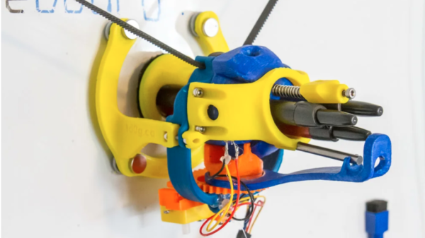
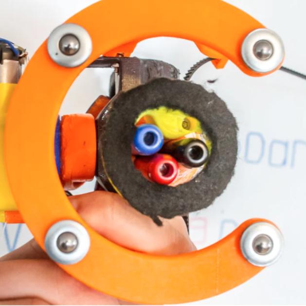
AutoWhiteboardBot’s business end, with three markers.
[td0g]’s AutoWhiteboardBot is not just any 3D printed whiteboard plotter, because it also sports a triple-marker carrier and on-board eraser! The device itself hangs from stepper motors, which take care of moving the plotter across the whiteboard, and the trick to making the three colors work was to incorporate retractable dry-erase markers. A spherical Geneva drive-based assembly on the plotter rotates the pen cartridge, and a plunger activates the chosen color. Erasing, arguably the easiest thing to do on a whiteboard, is done by a piece of felt. 3D printed parts are on Thingiverse and [td0g] says software is coming soon. It’s a clever device, especially the method of accommodating multiple colors with retractable markers.
AutoWhiteboardBot hangs from motors which pull it around, but we’ve also seen a SCARA-type robot writing away on a whiteboard. Watch the video embedded below, which begins with sped-up footage of AutoWhiteboardBot drawing in different colors as it slides across the board surface.
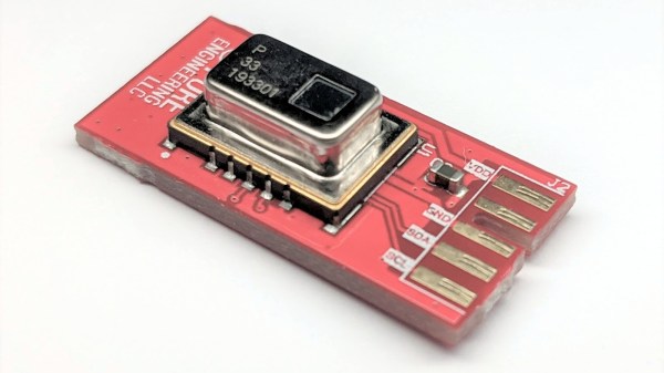
Panasonic’s Grid-EYE sensor is essentially a low-cost 8×8 thermal imager with a 60 degree field of view, and a nice breakout board makes it much easier to integrate into projects. [Pure Engineering] has created an updated version of their handy breakout board for the Grid-EYE and are currently accepting orders. The new breakout board is well under an inch square and called the GridEye2 (not to be confused with the name of the main component, the AMG8833 Grid-EYE by Panasonic.)
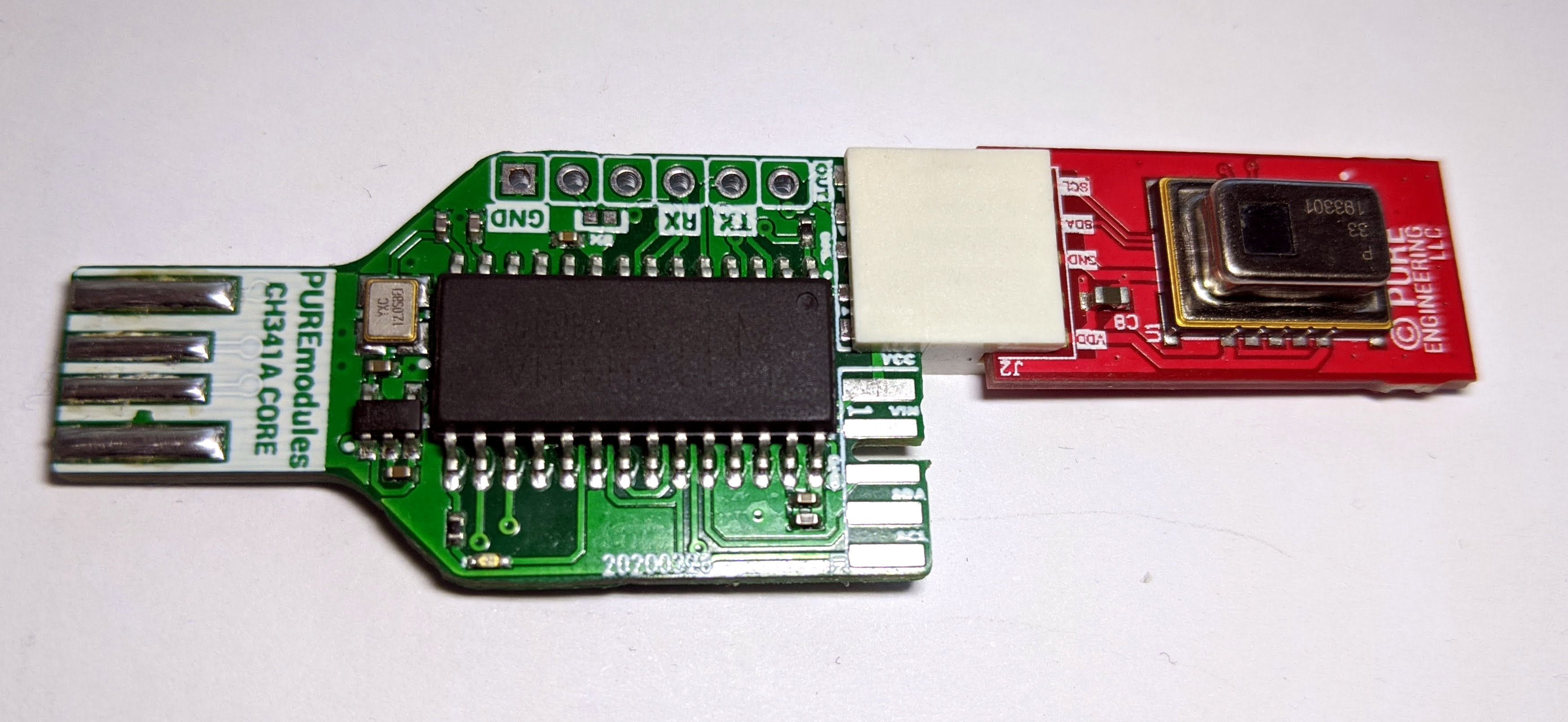
GridEye2 connected to CH341A dev board, allowing easy PC interface over USB.
A common way to interface with the Grid-EYE is over I2C, but to make connecting and developing on a PC more straightforward, [Pure Engineering] has made sure the new unit can plug right into their (optional) CH341A development board to provide a USB interface. Getting up and running on a Linux box is then as simple as installing the Linux drivers for the CH341A, and using sample C code to start reading thermal data from an attached GridEye2 board.