Simple Tips For Better 3D-Printed Enclosures

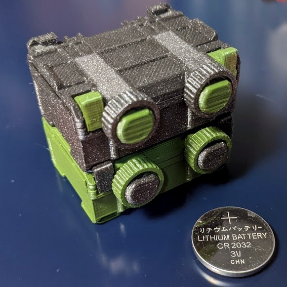
3D printing can be great for making enclosures, and following some simple guidelines can help the whole process go much smoother. 3D Hubs has an article on designing printed enclosures that has clear steps and tips to get enclosures coming out right the first time. 3D Hubs offers 3D printing and other services, and the article starts with a short roundup of fabrication methods but the rest is a solid set of tips applicable to anyone.

The first recommendation is to model the contents of the enclosure as a way to help ensure everything fits as it should, and try to discover problems as early as possible during the design phase, before anything gets actually printed. We’ve seen how a PCB that doesn’t take the enclosure into account risks needing a redesign, because there are some issues an enclosure just can’t fix.

The rest of their advice boils down to concrete design guidelines about wall thickness (they recommend 2 mm or more), clearances (allow a minimum of 0.5 mm between internal components and enclosure), and how to size holes for fasteners, clips, or ports. These numbers aren’t absolute minimums, but good baseline values to avoid surprises.

One final useful tip is that using a uniform wall thickness throughout the enclosure is general good practice. While this isn’t strictly necessary for successful 3D printing, it will make life easier if the enclosure ever moves to injection molding. Want to know more? Our own Bob Baddeley has an excellent primer on injection molding, and his been-there-done-that perspective is invaluable.

Art of 3D printer in the middle of printing a Hackaday Jolly Wrencher logo

3D Printering: The Things Printers (Don’t) Do

3D printers are amazing things, but if one judges solely by the successes that get showcased online, it can look as through anything at all is possible. Yet in many ways, 3D printers are actually quite limited. Because success looks easy and no one showcases failure, people can end up with lopsided ideas of what is realistic. This isn’t surprising; behind every shining 3D print that pushes the boundaries of the technology, there are misprints and test pieces piled just out of sight.

If you have ever considered getting into 3D printing, or are wondering what kinds of expectations are realistic, read on because I am going to explain where objects come from, and how to recognize whether something is a good (or bad) fit for 3D printing. The important thing to understand is that printers have limitations, and to get a working idea of what those limitations are. The result will be a better understanding of what they can do, and what problems they can reliably solve.

3D Printers Have Limits

I recently had a talk with someone who wanted to know if a 3D printer could help with a problem they had. As I listened to them describe their needs, I realized I had in a way heard it all before many times.

My colleague actually had a fairly good idea of what printers could do, in theory. But they had very little grasp of what printers did not do, and that disconnect left them a bit adrift when it came to practical applications. To help address this gap, here are some tips that can give anyone a working understanding of the things 3D printers do not do well. Continue reading “3D Printering: The Things Printers (Don’t) Do”

How To Improve A Smart Motor? Make It Bigger!

Brushless motors can offer impressive torque-to-size ratios, and when combined with complex drive control and sensor feedback, exciting things become possible that expand the usual ideas of what motors can accomplish. For example, to use a DC motor in a robot leg, one might expect to need a gearbox, a motor driver, plus an encoder for position sensing. If smooth, organic motion is desired, some sort of compliant mechanical design would be involved as well. But motors like the IQ Vertiq 6806 offered by [IQ Motion Control] challenge those assumptions. By combining a high-torque brushless DC motor, advanced controller, and position sensing into an integrated device, things like improved drone performance and direct-drive robotic legs like those of the Mini Cheetah become possible.

IQ Vertiq 6806 brushless DC motor with integrated controller, driver, and position sensing.

First, the bad news: these are not cheap motors. The IQ Vertiq 6806 costs $399 USD each through the Crowd Supply pre-order ($1499 for four), but they aren’t overpriced for what they are. The cost compares favorably with other motors and controllers of the same class. A little further than halfway down the Crowd Supply page, [IQ Motion Control] makes a pretty good case for itself by comparing features with other solutions. Still, these are not likely to be anyone’s weekend impulse purchase.

So how do these smart motors work? They have two basic operating modes: Speed and Position, each of which requires different firmware, and which one to use depends on the intended application.

The “Speed” firmware is designed with driving propeller loads in mind, and works a lot like any other brushless DC motor with an ESC (electronic speed control) on something like a drone or other UAV. But while the unit can be given throttle or speed control signals like any other motor, it can also do things like accept commands in terms of thrust. In other words, an aircraft’s flight controller can communicate to motors directly in thrust units, instead of a speed control signal whose actual effect is subject to variances like motor voltage level.

The “Position” mode has the motor function like a servo with adjustable torque, which is perfect for direct drive applications like robotic legs. The position sensing also allows for a few neat tricks, like the ability to use the motors as inputs. Embedded below are two short videos showcasing both of these features, so check them out.

Continue reading “How To Improve A Smart Motor? Make It Bigger!”

As Facebook Tightens Their Grip On VR, Jailbreaking Looks More Likely

The Quest 2 wireless VR headset by Oculus was recently released, and improves on the one-and-a-half year old Quest mainly in terms of computing power and screen resolution. But Oculus is owned by Facebook, a fact that Facebook is increasingly keen on making very clear. The emerging scene is one that looks familiar: a successful hardware device, and a manufacturer that wants to keep users in a walled garden while fully controlling how the device can be used. Oculus started out very differently, but the writing has been on the wall for a while. Rooting and jailbreaking the Quest 2 seems inevitable, but what will happen then? Continue reading “As Facebook Tightens Their Grip On VR, Jailbreaking Looks More Likely”

Low-Tech Fix Saves Expensive, High-Tech TV From Junk Pile

Wiggling this connector caused the backlight to turn off and on.

[Tweepy]’s TV stopped working, and the experience is a brief reminder that if a modern appliance fails, it is worth taking a look inside because the failure might be something simple. In this case, the dead TV was actually a dead LED backlight, and the fix was so embarrassingly simple that [Tweepy] is tempted to chalk it up to negligently poor DFM (design for manufacture) at best, or even some kind of effort at planned obsolescence at worst.

What happened is this: the TV appeared to stop working, but one could still make out screen content while shining a bright light on the screen. Seeing this, [Tweepy] deduced that the backlight had failed, and opened up the device to see if it could be repaired. However, the reason for the backlight failure was a surprise. It was not the power supply, nor even any of the LEDs themselves; the whole backlight wouldn’t turn on because of a cheap little PCB-to-PCB connector, and the two small spring contacts inside that had failed.

The failed connector, once cut open, showed contacts in poor condition (click to enlarge). It was ditched for a soldered connection, and the TV lived again.

From the outside things looked okay, but wiggling the connector made the backlight turn on and off, so the connection was clearly bad. Investigating further, [Tweepy] saw that the contact points of the PCBs and the two little conductors inside the connector showed clear signs of arcing and oxidation, leading to a poor connection that eventually failed, resulting in a useless TV. The fix wasn’t to clean the contacts; the correct fix was to replace the connector with a soldered connection.

Using that cheap little connector doubtlessly saved some assembly time at the factory, but it also led to failure within a fairly short amount of time. Had [Tweepy] not been handy with a screwdriver (or not bothered to investigate) the otherwise working TV would doubtlessly have ended up in a landfill.

It serves as a good reminder to make some time to investigate failures of appliances, even if one’s repair skills are limited, because the problem might be a simple one. Planned obsolescence is a tempting doorstep upon which to dump failures like this, but a good case can be made that planned obsolescence isn’t really a thing, even if manufacturers compromising products in one way or another certainly is.

Improved Flexible Build Plate For SLA Is Ready To Rock

The Elegoo Mars is an affordable SLA (resin-based) 3D printer, and there are probably few that have seen more mods and experimentation than [Jan Mrázek]’s machine. The final design of his DIY flexible build plate is a refinement of his original proof of concept, which proved a flexible build platform can be every bit as useful on an SLA printer as it is for FDM; instead of chiseling parts off a rigid build platform, simply pop the flexible steel sheet off the magnetic base and flex it slightly for a much easier part removal process. His original design worked, but had a few rough edges that have since been ironed out.

[Jan]’s magnetic build platform.
We love how [Jan] walks through all of the design elements and explains what worked and what didn’t. For example, originally he used a galvanized steel sheet which was easy enough to work with, but ended up not being a viable choice because once it’s bent, it stays bent. Spring steel is a much better material for a flexible build platform, but is harder for a hobbyist to cut.

Fortunately, it’s a simple job for any metal fabrication shop and [Jan] got a variety of thicknesses cut very cheaply. It turns out that the sweet spot is 0.3 mm (although 0.2 mm is a better choice for particularly fragile parts.) [Jan] also suggests cutting the sheet a few millimeters larger than the build platform; it’s much easier to peel the sheet off the magnetic base when one can get a fingertip under an edge, after all.

The magnetic base that the steel sheet sticks to is very simple: [Jan] converted a stock build platform by mounting an array of 20 x 20 x 1 mm magnets with 3M adhesive mounting tape. He was worried that resin might seep in between the magnets and cause a problem, perhaps even interfering with the adhesive; but so far it seems to be working very well. Resin is viscous enough that it never penetrates far into the gaps, and no effect on the adhesive has been observed so far.

Watch how easily parts are removed in the short video embedded below, in which [Jan] demonstrates his latest platform design.

Continue reading “Improved Flexible Build Plate For SLA Is Ready To Rock”

Complex Wood Joints, Thanks To New Software’s Interactive Features

Artfully-crafted wooden joints that fit together like puzzle pieces and need neither glue nor nails is fascinating stuff, but to call the process of designing and manufacturing them by hand “time-consuming” would be an understatement. To change that, a research team from the University of Tokyo presented Tsugite, a software system for interactively designing and fabricating complex wooden joints. It’s named after the Japanese word for joinery, and aims to make the design and manufacture of glue and fastener-free joints much easier than it otherwise would be.

Three-way joint that requires no glue or fasteners.

It looks like the software is so far only a research project and not something that can be downloaded The software is available on GitHub and the approach it takes is interesting. This downloadable PDF explains how the software deals with the problem of how to make such a task interactive and practical.

The clever bit is that the software not only provides design assistance for the joints themselves in a WYSIWYG (what you see is what you get) interface, but also generates real-time feedback based on using a three-axis CNC tool as the manufacturing method. This means that the system understands the constraints that come from the fabrication method, and incorporates that into design feedback.

The two main limitations of using a three-axis CNC are that the cutting tool can only approach the material from above, and that standard milling bits cannot create sharp inner corners; they will have a rounded fillet the same radius as the cutting bit. Design can be done manually, or by selecting joints from a pre-defined gallery. Once the design is complete, the system generates the toolpaths for manufacture.

Currently, Tsugite is limited to single joints meant for frame structures, but there’s no reason it couldn’t expand beyond that scope. A video to accompany the paper is embedded below, it’s short and concise and shows the software in action, so be sure to give it a look.

Continue reading “Complex Wood Joints, Thanks To New Software’s Interactive Features”