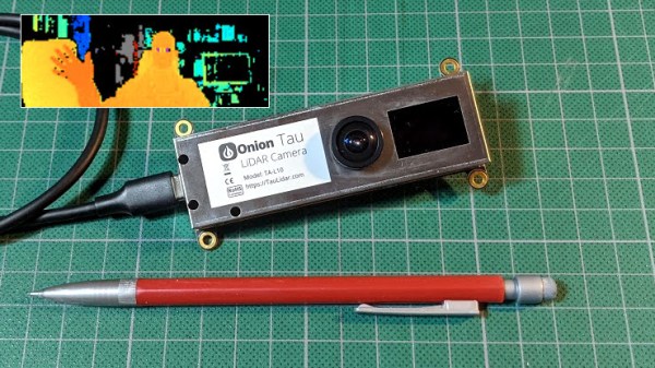
The Onion Tau LiDAR Camera is a small, time-of-flight (ToF) based depth-sensing camera that looks and works a little like a USB webcam, but with a really big difference: frames from the Tau include 160 x 60 “pixels” of depth information as well as greyscale. This data is easily accessed via a Python API, and example scripts make it easy to get up and running quickly. The goal is to be an affordable and easy to use option for projects that could benefit from depth sensing.
When the Tau was announced on Crowd Supply, I immediately placed a pre-order for about $180. Since then, the folks at Onion were kind enough to send me a pre-production unit, and I’ve been playing around with the device to get an idea of how it acts, and to build an idea of what kind of projects it would be a good fit for. Here is what I’ve learned so far.
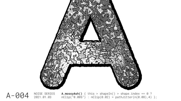
Perlin noise is best explained in visual terms: if a 2D slice of truly random noise looks like even and harsh static, then a random 2D slice of Perlin noise will have a natural-looking blotchy structure, with smooth gradients. [Jacob Stanton] used Perlin noise as the starting point for creating some interesting generative vector art that shows off all kinds of different visuals. [Jacob] found that his results often exhibited a natural quality, with the visuals evoking a sense of things like moss, scales, hills, fur, and “other things too strange to describe.”
The art project [Jacob] created from it all is a series of posters showcasing some of the more striking examples, each of which displays an “A” modified in a different way. A few are shown here, and a collection of other results is also available.
Perlin noise was created by Ken Perlin while working on the original Tron movie in the early 80s, and came from a frustration with the look of computer generated imagery of the time. His work had a tremendous and lasting impact, and was instrumental to artists creating more natural-looking textures. Processing has a Perlin noise function, which was in fact [Jacob]’s starting point for this whole project.
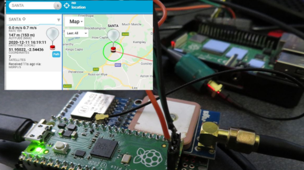
[Dave Akerman]’s ongoing high altitude balloon (HAB) work is outstanding, and we’re all enriched by the fact that he documents his work like he does. Recently, [Dave] wrote about his balloon tracker based on the Raspberry Pi Pico, whose capabilities brought a couple interesting features to the table.
In a way, HAB trackers have a fairly simple job: read sensors such as GPS and constantly relay that data to someone on the ground so that the balloon’s location can be tracked, and the hardware recovered when it ultimately returns to Earth. There are a lot of different ways to do this tracking, and one thing [Dave] enjoys is getting his hands on a new board and making a HAB tracker out of it. That’s exactly what he has done with the Raspberry Pi Pico.
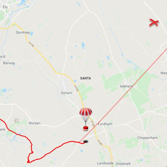
Nothing builds familiarity like actually using a part, and the Pico had some useful things to contribute to a HAB tracker application. For one thing, the Pico has an onboard buck-boost converter that allows it to be powered from a relatively wide voltage range (~1.8 V to 5.5 V), so running it directly from batteries is both possible and desirable from a tracker perspective. But a really useful feature was possible thanks to the large amount of memory on the Pico: dynamic landing prediction.
[Dave] does landing prediction prior to launch based on environmental conditions, but it’s always better if the HAB tracker can also calculate its own prediction based on actual observed events and conditions. A typical microcontroller board like an Arduino doesn’t have enough memory to store the required data upon which to do such calculations, but the Pico does so easily. [Dave]’s new board transmits an updated landing site prediction along with all the rest of the telemetry, making the retrieval process much more reliable.
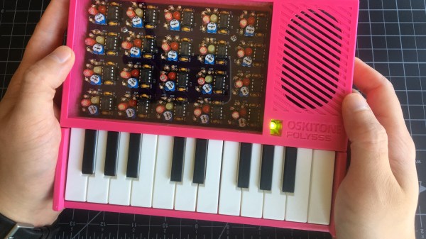
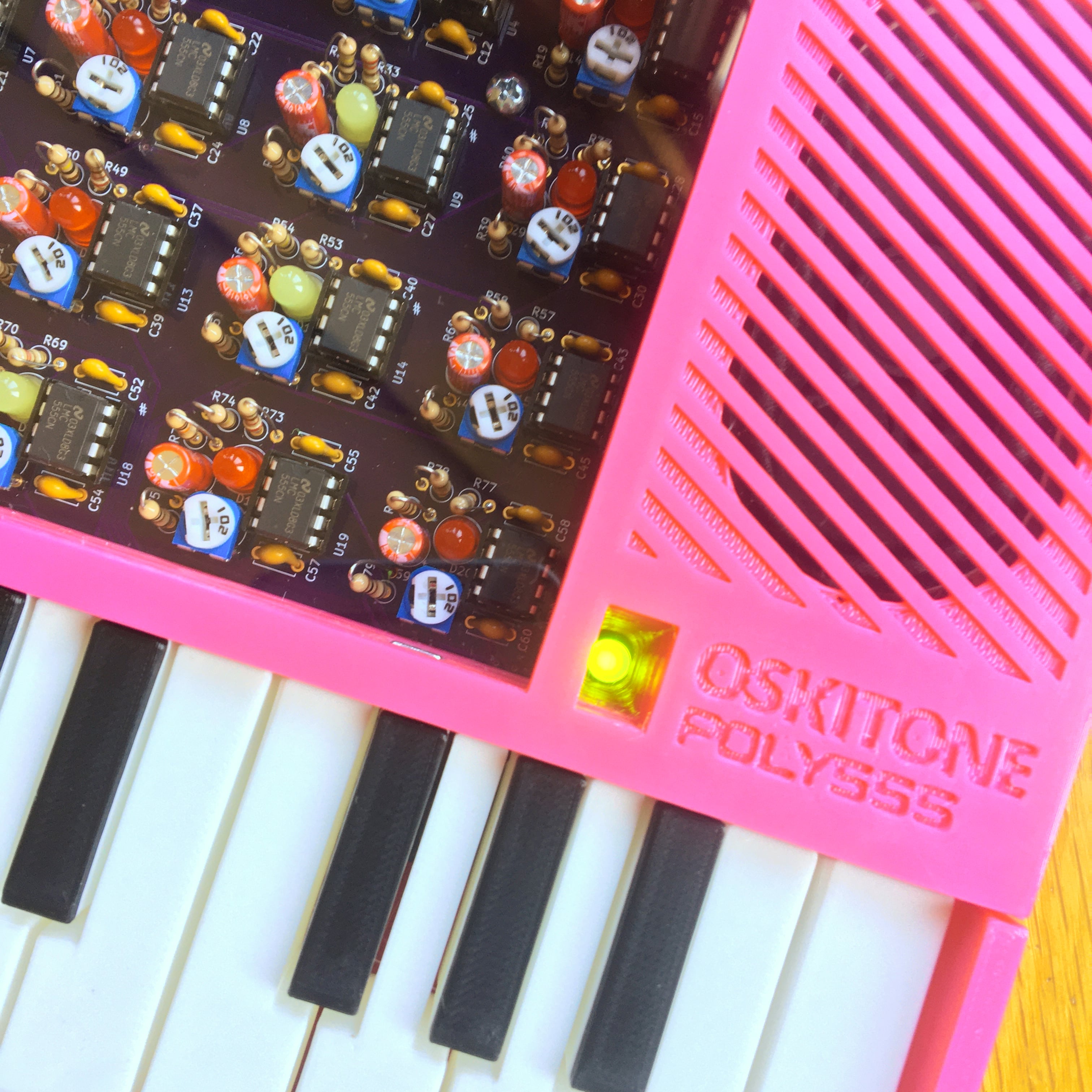
[Tommy]’s POLY555 is an analog, 20-note polyphonic synthesizer that makes heavy use of 3D printing and shows off some clever design. The POLY555, as well as [Tommy]’s earlier synth designs, are based around the 555 timer. But one 555 is one oscillator, which means only one note can be played at a time. To make the POLY555 polyphonic, [Tommy] took things to their logical extreme and simply added multiple 555s, expanding the capabilities while keeping the classic 555 synth heritage.
The real gem here is [Tommy]’s writeup. In it, he explains the various design choices and improvements that went into the POLY555, not just as an instrument, but as a kit intended to be produced and easy to assemble. Good DFM (Design For Manufacturability) takes time and effort, but pays off big time even for things made in relatively small quantities. Anything that reduces complexity, eliminates steps, or improves reliability is a change worth investigating.
For example, the volume wheel is not a thumbwheel pot. It is actually a 3D-printed piece attached to the same potentiometer that the 555s use for tuning; meaning one less part to keep track of in the bill of materials. It’s all a gold mine of tips for anyone looking at making more than just a handful of something, and a peek into the hard work that goes into designing something to be produced. [Tommy] even has a short section dedicated to abandoned or rejected ideas that didn’t make the cut, which is educational in itself. Want more? Good news! This isn’t the first time we’ve been delighted with [Tommy]’s prototyping and design discussions.
POLY555’s design files (OpenSCAD for enclosure and parts, and KiCad for schematic and PCB) as well as assembly guide are all available on GitHub, and STL files can be found on Thingiverse. [Tommy] sells partial and complete kits as well, so there’s something for everyone’s comfort level. Watch the POLY555 in action in the video, embedded below.
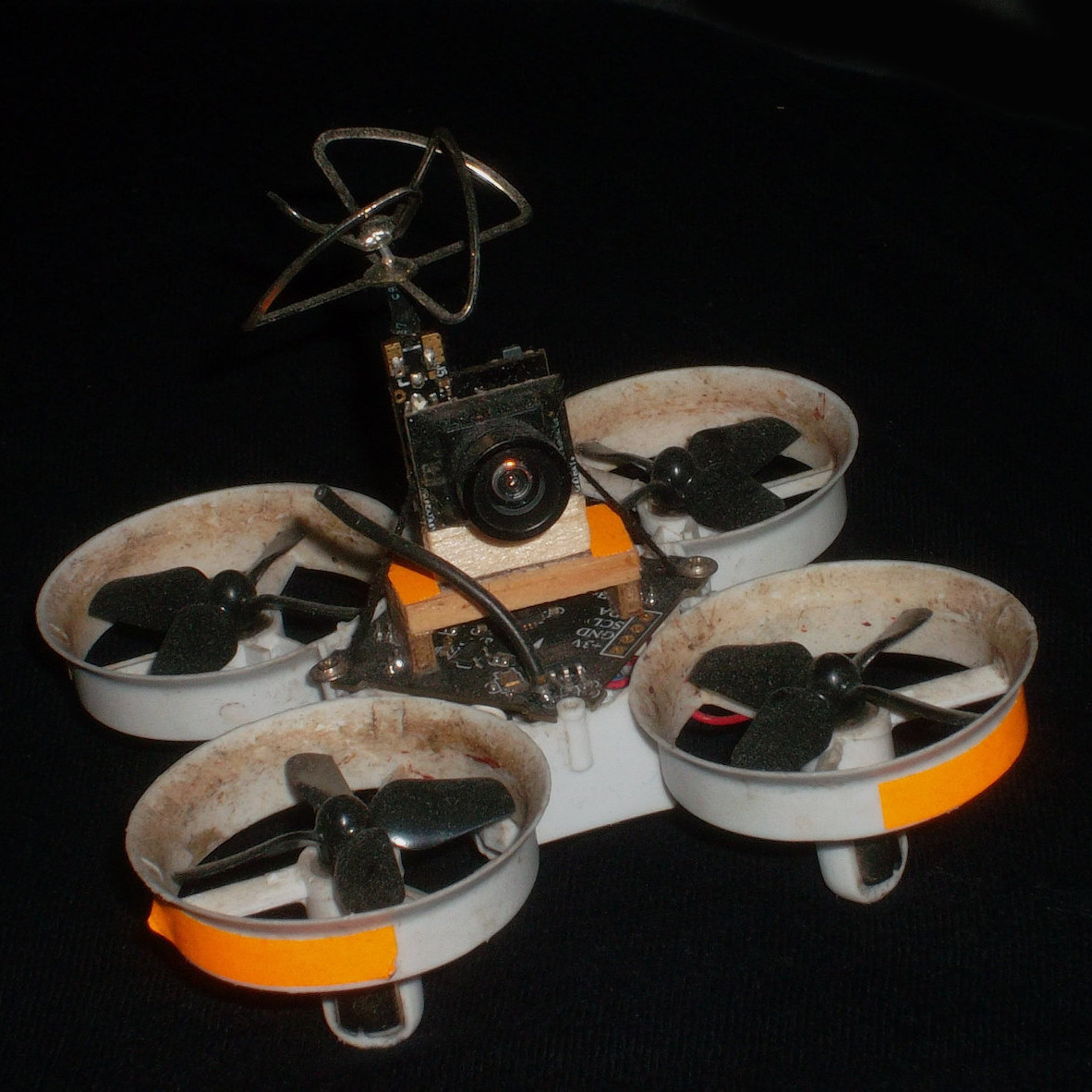
Lost aircraft are harder to find when they are physically small to begin with. Not only are they harder to see, but the smaller units lack features like GPS tracking; it’s not normally possible to add it to a tiny aircraft that can’t handle much more than its own weight in the first place. As a result, little lost quads tend to be trickier to recover in general.
Fluorescent tape adds negligible weight, and will glow brightly at night under a UV light.
The good news is that [Eric Brasseur] has shared some concise tips on how to more easily locate and recover lost aircraft, especially lightweight ones. Recovering aircraft is something every aircraft hobbyist has had to deal with in one way or another, but [Eric] really has gathered an impressive list of tricks and techniques, and some of them go into some really useful additional detail. It occurs to us that a lot of these tips could apply equally well to outdoor robots, or rovers.
Even simple techniques can be refined. For example, using bright colors on an aircraft is an obvious way to increase visibility, but some colors are better choices than others. Bright orange, white, and red are good choices because they are easily detected by the human eye while still being uncommon in nature. Violet, blue, and even cyan on the other hand may seem to be good choices when viewed indoors on a workbench, but if the quad is stuck in dark bushes, those colors will no longer stand out. Another good tip is to consider also adding a few patches of fluorescent tape to the aircraft. If all else fails, return at night with a UV lamp; those patches will glow brightly, and be easily seen from tens of meters.
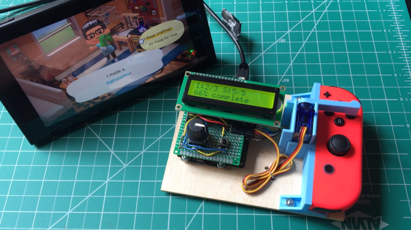
Press button, wait, press button again, repeat. There must be a better way! If that kind of interaction drives you nuts, you’ll probably appreciate [Tommy]’s buttonpusher, which has only one job: automate away some of the more boring parts of Nintendo’s Animal Crossing. On one hand the job the device does is very simple: press a button on the Nintendo joy-con in a preprogrammed pattern. There’s no feedback loop, it just dumbly presses and waits. But there are still quite a few interesting bits to this build.
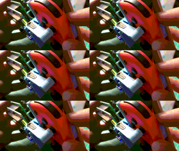
Rigid mounting combined with interfacing the actuator to the servo horn (instead of to the servo shaft) were the keys to reliable button pushing.
For one thing, [Tommy] discovered that the little 9g RC servo can reliably exert enough force to press the button on the joy-con with the right adapter. He had assumed the servo would be too weak to do the job without a greater mechanical advantage, but a simple hammer-style actuator that attaches to the servo horn easily does the job. Well, it does as long as the servo and joy-con are held rigidly; his first version allowed a little too much wiggle in how well the parts were held, and button presses didn’t quite register. With a 3D-printed fixture to rigidly mount both the servo and the joy-con, things were fine.
In the process of making buttonpusher, which uses CircuitPython, [Tommy] created a tool to automate away another pesky task he was running into: circuitpython_tools was created to automatically watch for code changes, convert the .py files into (smaller) MicroPython bytecode .mpy files, then automatically deploy to the board. This saved [Tommy] a lot of time and hassle during development, but it was only necessary because he quickly ran out of memory on his M0 Metro Express board, and couldn’t fit his code in any other way.
Still, it’s a good example of how one project can sometimes spawn others, and lead to all kinds of lessons learned. You can see buttonpusher automate the crafting process in Animal Crossing in the video, embedded below.
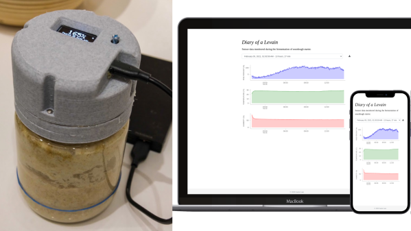
[Justin Lam] created a wonderfully-detailed writeup of his Smart Sourdough Lid project, which was created out of a desire to get better data on the progress and health of his sourdough starters, and to do so more efficiently. The result is a tidy, one-piece lid that constantly measures temperature, humidity, and height of the starter in the jar. Data is sent wirelessly for analysis, but there is also a handy OLED display on the top of the lid that shows immediately useful data like how much the starter has peaked, and how much time has passed since it did so.
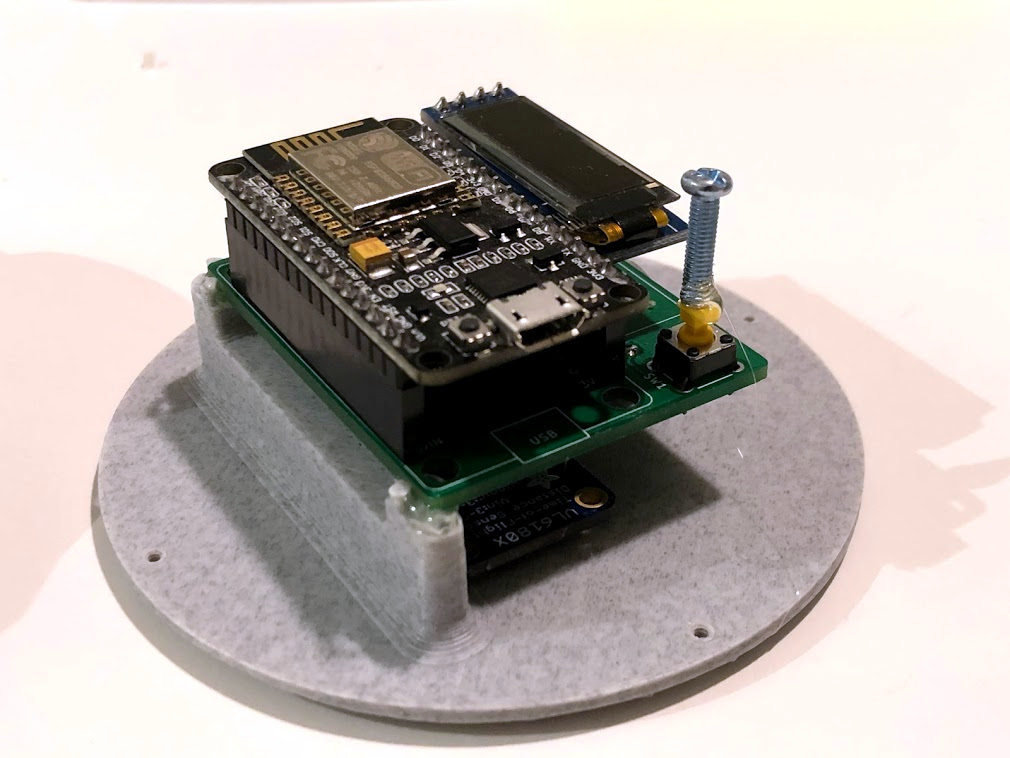
The PCB was optimized for size, and not designed with mounting in mind, so a hot-glued machine screw serves as a “button extender”. Issues like this can happen when enclosures are designed after the fact; it’s something to which we can all relate.
We really like how focused the design is, and the level of detail [Justin] goes into to explain his design decisions and describe how well they worked out. This isn’t [Justin]’s first kick at the can when it comes to getting data on his sourdough, after all. We remember his earlier work using computer vision to analyze sourdough starters, and he used what he learned to inform this new design; the smart lid is easier to use and handles data much more efficiently.
The project’s GitHub repository has all the information needed to build your own. The lid is ESP8266-based and integrates a VL6180X time-of-flight (ToF) distance sensor, DHT22 to sense temperature and humidity, and a small SSD1306 OLED display for data. A small custom PCB keeps the modules tidy, and a 3D-printed custom enclosure makes it one tidy package.
[Justin] also analyzes the results he obtained and talks about what they mean in the last part of his writeup, so if you’re into baking and interested in his findings, be sure to give that a look.