Closeup of unique pieces that make up the final scuplture.
The sculpture shown here is called Puzzle Cell Complex and was created by [Nervous System] as an art piece intended to be collaboratively constructed by conference attendees. The sculpture consists of sixty-nine unique flat panel pieces, each made from wood, which are then connected together without the need for tools by using plastic rivets. Everything fits into a suitcase and assembly documentation is a single page of simple instructions. The result is the wonderfully-curved gyroid pattern you see here.
The sculpture has numerous layers of design, not the least of which was determining how to make such an organically-curved shape using only flat panels. The five-foot assembled sculpture has a compelling shape, which results from the sixty-nine individual panels and how they fit together. These individual panel shapes have each been designed using a technique called variational surface cutting to minimize distortion, resulting in their meandering, puzzle-piece-like outlines. Each panel also has its own unique pattern of cutouts within itself, which makes the panels lighter and easier to bend without sacrificing strength. The short video embedded below shows the finished sculpture in all its glory.
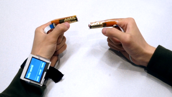
The fingertips are covered in touch sensors, each intended to be tapped by the thumbtip of the same hand.
Touch-typing with thumbs on a mobile phone keyboard is a pretty familiar way to input text, and that is part of what led to BiTipText, a method of allowing bimanual text input using fingertips. The idea is to treat the first segments of the index fingers as halves of a tiny keyboard, whose small imaginary keys are tapped with the thumbs. The prototype shown here was created to see how well the concept could work.
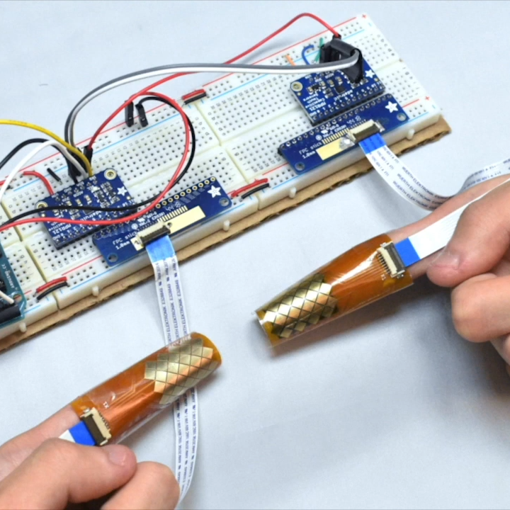
The prototype hardware uses touch sensors that can detect tap position with a high degree of accuracy, but the software side is where the real magic happens. Instead of hardcoding a QWERTY layout and training people to use it, the team instead ran tests to understand users’ natural expectations of which keys should be on which finger, and how exactly they should be laid out. This data led to an optimized layout, and when combined with predictive features, test participants could achieve an average text entry speed of 23.4 words per minute.
Judging by the prototype hardware, it’s understandable if one thinks the idea of fingertip keyboards may be a bit ahead of its time. But considering the increasingly “always on, always with you” nature of personal technology, the goal of the project was more about investigating ways for users to provide input in fast and subtle ways. It seems that the idea has some merit in principle. The project’s paper can be viewed online, and the video demonstration is embedded below.
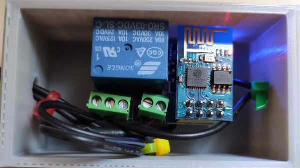
Sometimes connectivity problems go away by power cycling a router. It’s a simple but inconvenient solution to a problem that shouldn’t exist, but that didn’t stop [Mike Diamond] from automating it for a few bucks in parts. The three-dollar router rebooter may be a simple device with only one job, but it’s well documented and worth a look.
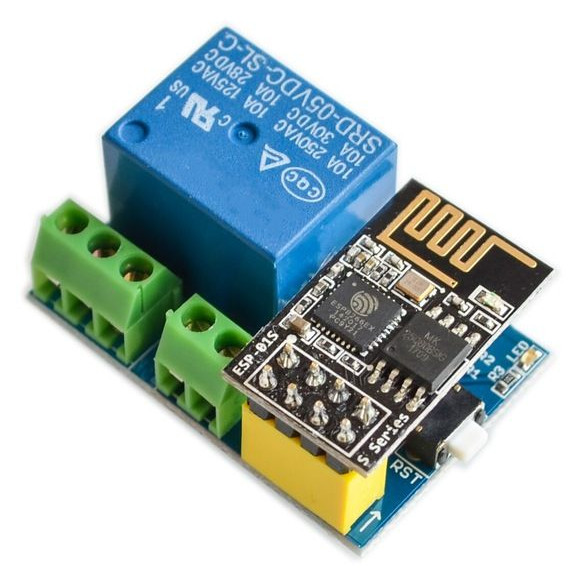
The device is an ESP8266 board configured to try to reach Google periodically via the local wireless network. If Google cannot be reached, the board assumes a reboot is needed and disconnects the 12 V power supply from the router by using a relay. Then, after a delay, power is re-connected and all of one’s problems are over until the next time it happens. [Mike] used a relay module that has built-in screw terminals and a socket for the ESP8266-01, so it looks like the whole device can be put together without soldering a thing.
While the code for making this happen may sound trivial, [Mike] nevertheless delves into documenting it. It makes a great example of how to implement a simple event-driven finite state machine in a way that’s clear and concise. By structuring the code so that there is a finite number of specific states the device can be in (router power on, router power off, and testing connection) and by defining exactly how and when the device switches between those states, operation and troubleshooting becomes a much more manageable job. Another great example is this IoT Garage Door Opener project. If you’re programming devices that interface to physical things, these techniques are definitely good practice.
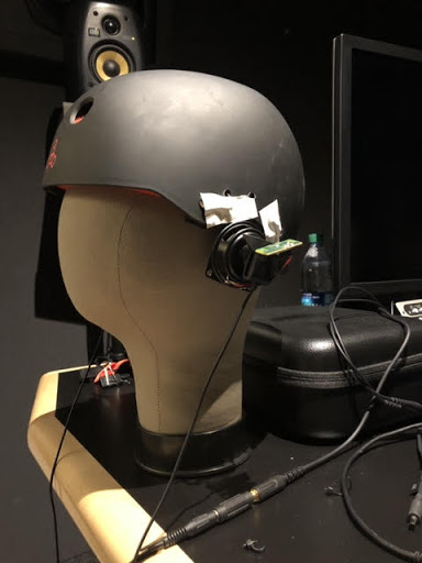
The Valve Index VR headset incorporates a number of innovations, one of which is the distinctive off-ear speakers instead of headphones or earbuds. [Emily Ridgway] of Valve shared the design and evolution of this unusual system in a deep dive into the elements of the Index headset. [Emily] explains exactly what they were trying to achieve, how they determined what was and wasn’t important to deliver good sound in a VR environment, and what they were able to accomplish.
First prototype, a proof-of-concept that validated the basic idea and benefits of off-ear audio delivery.
Early research showed that audio was extremely important to providing a person with a good sense of immersion in a VR environment, but delivering a VR-optimized audio experience involved quite a few interesting problems that were not solved with the usual solutions of headphones or earbuds. Headphones and earbuds are optimized to deliver music and entertainment sounds, and it turns out that these aren’t quite up to delivering on everything Valve determined was important in VR.
The human brain is extremely good at using subtle cues to determine whether sounds are “real” or not, and all kinds of details come into play. For example, one’s ear shape, head shape, and facial geometry all add a specific tonal signature to incoming sounds that the brain expects to encounter. It not only helps to localize sounds, but the brain uses their presence (or absence) in deciding how “real” sounds are. Using ear buds to deliver sound directly into ear canals bypasses much of this, and the brain more readily treats such sounds as “not real” or even seeming to come from within one’s head, even if the sound itself — such as footsteps behind one’s back — is physically simulated with a high degree of accuracy. This and other issues were the focus of multiple prototypes and plenty of testing. Interestingly, good audio for VR is not all about being as natural as possible. For example, low frequencies do not occur very often in nature, but good bass is critical to delivering a sense of scale and impact, and plucking emotional strings.
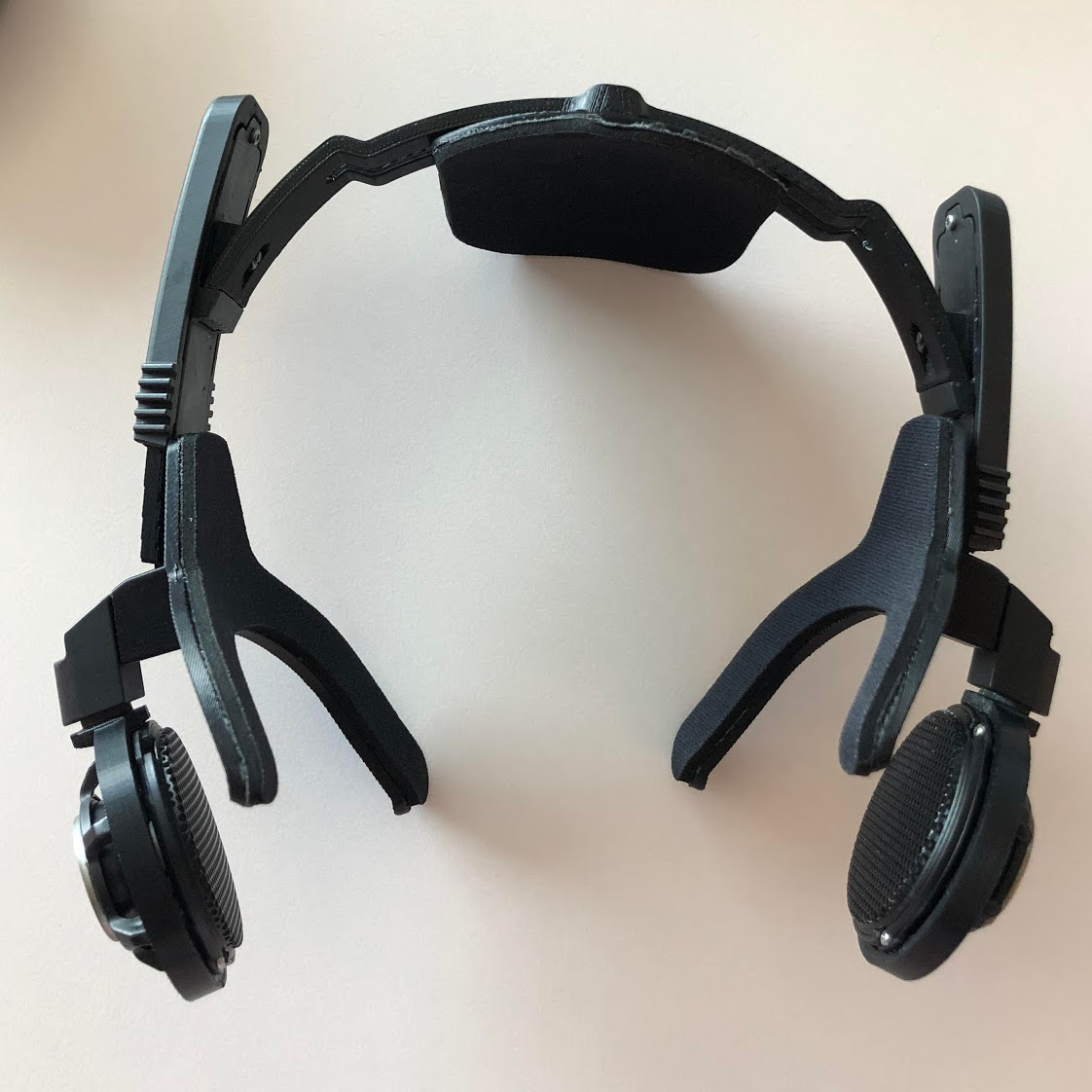
“Hummingbird” prototype using BMR drivers. Over twenty were made and lent to colleagues to test at home. No one wanted to give them back.
The first prototype demonstrated the value of testing a concept as early as possible, and it wasn’t anything fancy. Two small speakers mounted on a skateboard helmet validated the idea of off-ear audio delivery. It wasn’t perfect: the speakers were too heavy, too big, too sensitive to variation in placement, and had poor bass response. But the results were positive enough to warrant more work.
In the end, what ended up in the Index headset is a system that leans heavily on Balanced Mode Radiator (BMR) speaker design. Cambridge Audio has a short and sweet description of how BMR works; it can be thought of as a hybrid between a traditional pistonic speaker drivers and flat-panel speakers, and the final design was able to deliver on all the truly important parts of delivering immersive VR audio in a room-scale environment.
As anyone familiar with engineering and design knows, everything is a tradeoff, and that fact is probably most apparent in cutting-edge technologies. For example, when Valve did a deep dive into field of view (FOV) in head-mounted displays, we saw just how complex balancing different features and tradeoffs could be.
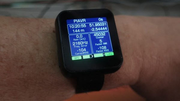
High Altitude Balloons (HAB) are a great way to get all kinds of data and shoot great photos and video, but what goes up must come down. Once the equipment has landed, one must track it down. GPS and LoRA, with its long wireless range and ease of use, are invaluable tools in tracking payloads that have returned to Earth. [Dave Akerman] has made handheld receivers to guide him to payloads, but wanted something even smaller; ideally something that could be worn on the wrist.
Not only is the new firmware functional, but it’s got a wonderful user interface. GitHub repository for the new firmware is here, and you can see the UI in action in the brief video embedded below.
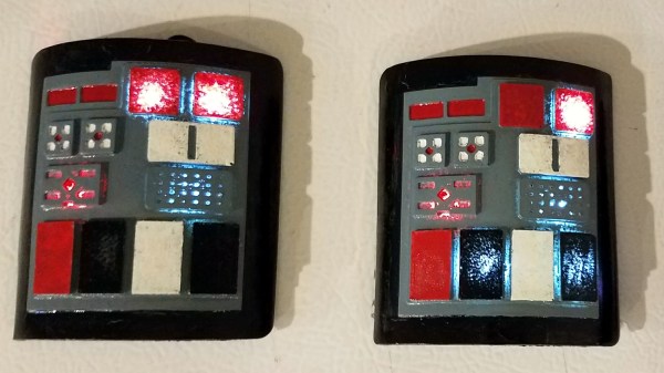
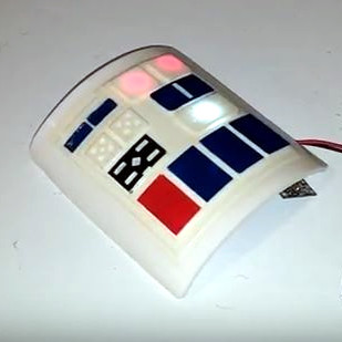
Etsy is a service aimed at providing a way for makers of handmade items to sell them online. [Bithead] closed up shop earlier this year and wrote up an interesting perspective on what did and didn’t work out. The main market for [Bithead]’s store was Star Wars cosplayers, because it all started with some Star Wars inspired com pads, some of which are pictured here.
One thing [Bithead] felt worked well overall was to “think big, start small, and scale fast.” In essence, bootstrap things by selling inventory on hand and carefully monitoring demand, then if demand is sustained, ramp up to larger batches, which are more efficient. The risk of making larger part orders and carrying more stock on hand is offset by the reliable demand. Waiting until solid data on reliable demand is available means missing out on early sales, but it’s a low risk approach that works well for niche products that have little or no real competition.
A couple things that didn’t work out were efforts to follow Etsy’s advice to add more products to attract a wider audience, and to try out tools for offering discounts and incentives aimed at turning abandoned carts into sales. Neither went well. The first resulted in adding items that sold poorly, diluted the focus of the store, and incurred a cost for each listing. The second never seemed to have any impact on sales whatsoever. Perhaps there is a place for these efforts, but [Bithead]’s niche market wasn’t it.
It’s a good read about how things went for an Etsy store that served a niche audience over three years. The perspective and experiences might be useful to anyone looking to turn a bright idea into something sold online, so if you’re at all interested, take a few minutes to check it out.
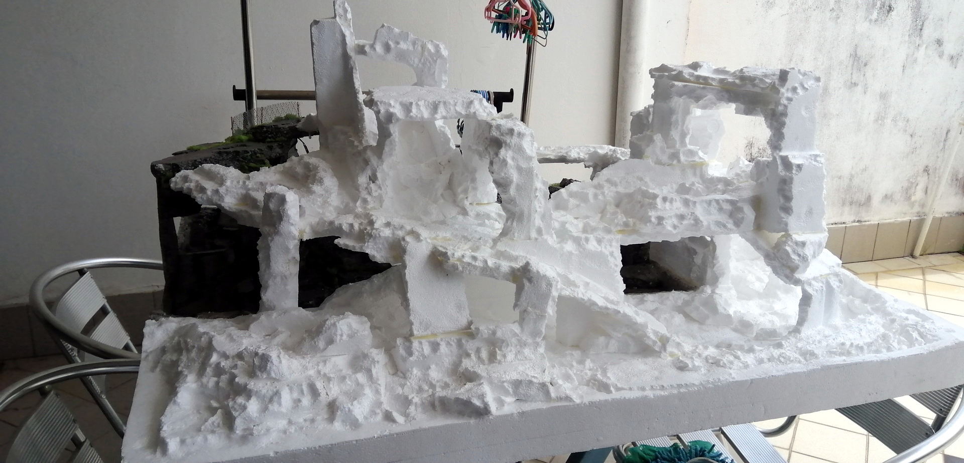
What does one do with tiny 1:35 scale remote controlled off-road vehicles? Build appropriately-tiny tracks for them to drive on, of course. That’s exactly what [David] did when he created his fantastic rock crawling track that he has dubbed the ‘4×4 Arena’, and what’s even better is that he used leftover foam inserts and acrylic paints and materials to do it, and didn’t have to spend a penny.
The original track is only just visible in the back; the new track expands it considerably.
This isn’t [David]’s first track. He originally made a smaller rock-crawling track he called Rubble Wasteland for the tiny vehicles, and he liked it so much he expanded it considerably. The new track builds on the original and is three levels deep, sports tight cave-like passages, tunnels, tricky climbs, and and realistic terrain textures.
An enormous photo gallery is right here, and other than the first and final images, it’s roughly in chronological build order. If your curiosity has been piqued about the tiny 1:35 scale remote controlled vehicles that this track is built for, around gallery page nine is where pictures of what makes these tiny things tick begins.