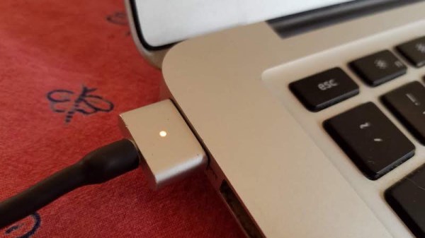
[Steve Chamberlin] has a spiffy solar-charged 12 V battery that he was eager to use to power his laptop, but ran into a glitch. His MacBook Pro uses Apple’s MagSafe 2 connector for power, but plugging the AC adapter into the battery via a 110 VAC inverter seemed awfully inefficient. It would be much better to plug it into the battery directly, but that also was a problem. While Apple has a number of DC power adapters intended for automotive use, none exist for the MagSafe 2 connector [Steve]’s mid-2014 MacBook Pro uses. His solution was to roll his own MagSafe charger with 12 VDC input.
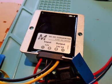 Since MagSafe connectors are proprietary, his first duty was to salvage one from a broken wall charger. After cleaning up the wires and repairing any frayed bits, it was time to choose a DC-DC converter to go between the MagSafe connector and the battery. The battery is nominally 12 volts, so the input of the DC-DC converter was easy to choose, but the output was a bit uncertain. Figuring out what the MagSafe connector expects took a little educated guesswork.
The original AC adapter attached to the charger claimed an output of 20 volts, another Apple adapter claimed a 14.85 V output, and a third-party adapter said 16.5 volts. [Steve] figured that the MagSafe connectors seemed fine with anything in the 15 to 20 V range, so it would be acceptable to use a 12 V to 19 V DC-DC boost converter which he had available. The result worked just fine, and [Steve] took measurements to verify that it is in fact much more efficient than had he took the easy way out with the inverter.
MagSafe has been displaced by USB-C nowadays, but there are plenty of MagSafe devices still kicking around. In a pinch, keep in mind that a little bit of filing or grinding is all that’s needed to turn MagSafe 1 into MagSafe 2.