We all know how to block the DC offset of an AC signal — that just requires putting a capacitor in series, right? But what if the AC signal doesn’t alternate very often? In that case, things get a little more complicated.
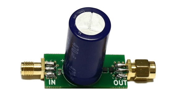
Or at least that’s what [Limpkin] discovered, which led him to design this low-frequency DC block. Having found that commercially available DC blocks typically have a cutoff frequency of 100 kHz, which is far too high to measure power rail ripple in his low-noise amplifier, he hit the books in search of an appropriate design. What he came up with is a non-polarized capacitor in series followed by a pair of PIN diodes shunted to ground. The diodes are in opposite polarities and serve to limit how much voltage passes out of the filter. The filter was designed for a cutoff frequency of 6.37 Hz, and [Limpkin]’s testing showed a 3-dB cutoff of 6.31 Hz — not bad. After some torture testing to make sure it wouldn’t blow up, he used it to measure the ripple on a bench power supply.
It’s a neat little circuit that ended up being a good learning experience, both for [Limpkin] and for us.