Track Those Leftovers With This Little Timer

We’ve all at some point in our lives opened the fridge door and immediately wished we hadn’t. A miasma of stench envelops us as we discover that last Saturday’s leftovers have been forgotten, and have gone off. If only we had some way to keep track of such things, to avoid such a stench-laden moment. Step forward [ThinkLearnDo], with a little timer designed for exactly that purpose.

The operation is simple enough, press the button and place the unit on top of the container with the leftovers in it. If you haven’t eaten the leftovers within a week, the LED will start blinking. The blink is a subtle reminder to deal with the old food before it becomes a problem.

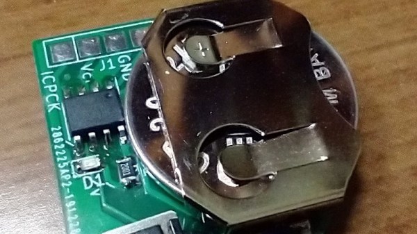
Onboard is a Holtek HT68F001 microcontroller with a coin cell for power, not much else is needed. The Holtek is an unusual choice, one of several brands of super-inexpensive Chinese microcontrollers we see less commonly than ATmegas and STM32s. This is exactly the place where such a minimal computer fits perfectly:  a way to add a little bit of smarts to a very cheap item with minimal strain on the BoM.

If these chips interest you, a while back we covered a run-down of the different families including the Holtek and the famous 3-cent Padauk chips.

How To Hide A Photo In A Photo

If you’ve ever read up on the basics of cryptography, you’ll be aware of steganography, the practice of hiding something inside something else. It’s a process that works with digital photographs and is the subject of an article by [Aryan Ebrahimpour]. It describes the process at a high level that’s easy to understand for non-maths-wizards. We’re sure Hackaday readers have plenty of their own ideas after reading it.

The process relies on the eye’s inability to see small changes at the LSB level to each pixel. In short, small changes in colour or brightness across an image are imperceptible to the naked eye but readable from the raw file with no problems. Thus the bits of a smaller bitmap can be placed in the LSB of each byte in a larger one, and the viewer is none the wiser.

We’re guessing that the increased noise in the image data would be detectable through mathematical analysis, but this should be enough to provide some fun. If you’d like a closer look, there’s even some code to play with. Meanwhile as we’re on the topic, this isn’t the first time Hackaday have touched on steganography.

Clever Stereo Camera Uses Sony Wireless Camera Modules

Stereophotography cameras are difficult to find, so we’re indebted to [DragonSkyRunner] for sharing their build of an exceptionally high-quality example. A stereo camera has two separate lenses and sensors a fixed distance apart, such that when the two resulting images are viewed individually with each eye there is a 3D effect. This camera takes two individual Sony cameras and mounts them on a well-designed wooden chassis, but that simple description hides a much more interesting and complex reality.

Sony once tested photography waters with the QX series — pair of unusual mirrorless camera models which took the form of just the sensor and lens.  A wireless connection to a smartphone allows for display and data transfer. This build uses two of these, with a pair of Android-running Odroid C2s standing in for the smartphones. Their HDMI video outputs are captured by a pair of HDMI capture devices hooked up to a Raspberry Pi 4, and there are a couple of Arduinos that simulate mouse inputs to the Odroids. It’s a bit of a Rube Goldberg device, but it allows the system to use Sony’s original camera software. An especially neat feature is that the camera unit and display unit can be parted for remote photography, making it an extremely versatile camera.

It’s good to see a stereo photography camera designed specifically for high-quality photography, previous ones we’ve seen have been closer to machine vision systems.

Super Simple Scope Shambles Solution

Sometimes the projects we write up for Hackaday require their creators to produce pages of technical explanation, while others need only rely on the elegance of the hack itself. The Scope Probe Caddy from [Tonyo] has probably one of the shortest write-ups we’ve linked to from a Hackaday piece, because its utility is self-evident just by looking at it.

Scope probe connector with 3d printed organiser attached.
The Hackaday Rigol gets the caddy treatment.

It’s likely that everyone who has owned an oscilloscope will have encountered this problem: that multiple ‘scope probes soon manifest themselves into a tangled mess, an unruly octopus which threatens to overwhelm your bench. The probe organizer is an extremely simple solution tot his problem, a 3D printed clip which fits over the probe connector and into which the probe itself can also slot.

The clip comes as an OpenSCAD file, which starts with a range of size definitions for different types of probe connector. The Rigol we have here isn’t among them, but a very quick measurement with the calipers allowed us to enter the size of a Rigol probe connector at 11.5 mm. It’s not often we make something we’re  writing up as we’re writing it, but in this case a quick bit of 3D printing and we too have tidy probe storage. With the addition of a cable tie or a small nut and bolt it’s assembled, and now helps make a Hackaday bench a little clearer.

Once you’ve printed this organizer, you might want to turn your attention to the probe itself.

The Sinclair ZX Spectrum Turns 40

It’s an auspicious moment for retrocomputing fans, as it’s now four decades since the launch of the Sinclair ZX Spectrum. This budget British microcomputer was never the best of the bunch, but its runaway success and consequent huge software library made it the home computer to own in the UK. Here in 2022 it may live on only in 1980s nostalgia, but its legacy extends far beyond that as it provided an entire generation of tech-inclined youngsters with an affordable tool that would get them started on a lifetime of computing.

What Was 1982 Really Like?

Cover of Sincalir User, Sir Clive Sinclair as a magician
Sinclair User issue 3 captures the excitement surrounding the Spectrum launch.

There’s a popular meme among retro enthusiasts that the 1980s was a riot of colour, pixel artwork, synth music, and kitschy design. The reality was of growing up amid the shabby remnants of the 1970s with occasional glimpses of an exciting ’80s future. This was especially true for a tech-inclined early teen, as at the start of 1982 the home computer market had not yet reached its full mass-market potential. There were plenty of machines on offer but the exciting ones were the sole preserve of adults or kids with rich parents. Budget machines such as Sinclair’s ZX81 could give a taste of what was possible, but their technical limitations would soon become obvious to the experimenter.

1982 was going to change all that, with great excitement surrounding three machines. Here in the UK, the Acorn BBC Micro had been launched in December ’81, the Commodore 64 at the start of ’82, and here was Sinclair coming along with their answer in the form of first the rumour of a ZX82, and then the reality in the form of the Spectrum.

This new breed of machines all had a respectable quantity of memory, high-res (for the time!) colour graphics, and most importantly, sound. The BBC Micro was destined to be the school computer of choice and the 64 was the one everybody wanted, but the Spectrum was the machine you could reasonably expect to get if you managed to persuade your parents how educational it was going to be, because it was the cheapest at £125 (£470 in today’s money, or about $615). Continue reading “The Sinclair ZX Spectrum Turns 40”

Can You Identify This Mystery Unicode Glyph?

For anyone old enough to have worked with the hell of multiple incompatible character sets, Unicode has been a liberation; a true One Character Set To Contain Them All. We have so many Unicode characters to play with that there’s a fascinating pursuit in itself in probing at the obscure corners of what can be rendered on screen as a Unicode glyph. With so many disparate character sets having been brought together to make the Unicode standard there are plenty of unusual characters to choose from, and it’s one of them that [Jonathan Chan] has examined in detail.

U+237C ⍼, or the right angle with downwards zigzag arrow, is a mysterious Unicode symbol with no known use and from an unknown origin. XKCD featured it as a spoof “Larry Potter”, but as [Jonathan]’s analysis shows it’s proving impossible to narrow down where it came from. Mystical cult symbol? Or perhaps fiscal growth in an economy in which time runs downwards? Either way, when its lineage has been traced into the early 1990s with no answer to the question it appears that there may be a story behind it.

Hackaday readers never cease to amaze us with the breadth of their knowledge, ingenuity, and experience, so we think it’s not impossible that among you there may be people who will turn and pull a dusty computer manual from the shelf to give us the story behind this elusive glyph. We’d love to hear in the comments below.

Meanwhile if Unicode sparks your interest, we’ve given it a close look in the past.

Thanks [Jonty] for the tip.

A FET Oscilloscope Probe For Higher Frequencies

It’s a problem that has dogged electronic engineers since the first electrons were coaxed along a wire: that measuring instruments can themselves disrupt the operation of a circuit. Older multimeters for example had impedances low enough to pull resistor values, thus our multimeters today have high-impedance FET inputs. [Christoph] faced it with his oscilloscope probe, its input capacitance was high enough to put unacceptable load on a crystal oscillator and stop it oscillating. He thus built a FET input probe for higher RF frequencies, and its construction is an accessible view of wideband RF instrumentation design.

The circuit is a very simple one using a dual-gate FET, but the interest comes in the PCB and screening can design to ensure good RF performance. Off-the-shelf cans have four sides, so to accommodate the circuit one wall of the can had to be removed. The end result is a tiny PCB with miniature co-ax connectors for power and signal, which when characterised was found to have a 1.3 GHz bandwidth and a very low input capacitance.

If the language of RF design is foreign to you, may we recommend [Michael Ossmann]’s talk at a Superconference a few years ago.