Review: Inkplate 6PLUS

While the price of electronic paper has dropped considerably over the last few years, it’s still relatively expensive when compared to more traditional display technology. Accordingly, we’ve seen a lot of interest in recovering the e-paper displays used in electronic shelf labels and consumer e-readers from the likes of Amazon, Barnes & Noble, and Kobo. Unfortunately, while these devices can usually be purchased cheaply on the second hand market, liberating their displays is often too complex a task for the average tinkerer.

Enter the Inkplate. With their open hardware ESP32 development board that plugs into the e-paper displays salvaged from old e-readers, the team at e-radionica is able to turn what was essentially electronic waste into a WiFi-enabled multipurpose display that can be easily programmed using either the Arduino IDE or MicroPython. The $99 Inkplate 6 clearly struck a chord with the maker community, rocketing to 926% of its funding goal on Crowd Supply back in 2020. A year later e-radionica released the larger and more refined Inkplate 10, which managed to break 1,000% of its goal.

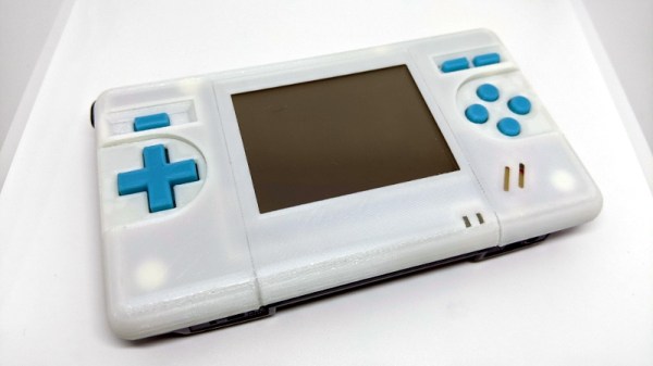
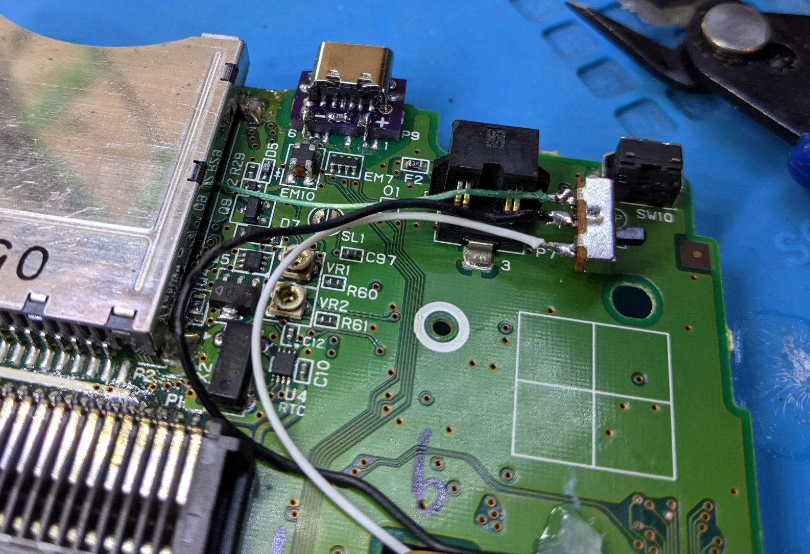
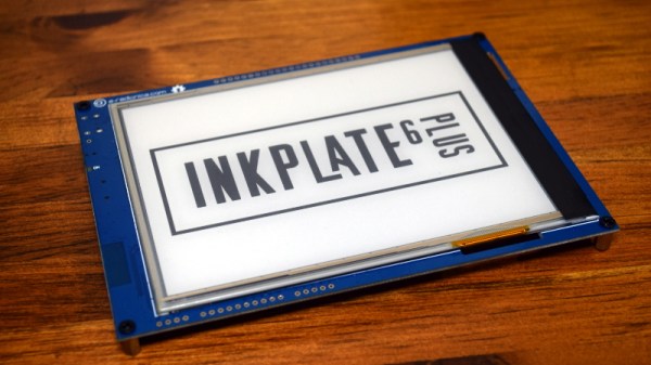
For 2021, the team is back with the Inkplate 6PLUS. This updated version of the original Inkplate incorporates the design additions from the Inkplate 10, such as the Real-Time-Clock, expanded GPIO, and USB-C port, and uses a display recycled from newer readers such as the Kindle Paperwhite. These e-paper panels are not only sharper and faster than their predecessors, but also feature touch support and LED front lighting; capabilities which e-radionica has taken full advantage of in the latest version of their software library.

With its Crowd Supply campaign recently crossing over the 100% mark, we got a chance to go hands-on with a prototype of the Inkplate 6PLUS to see how e-radionica’s latest hacker friendly e-paper development platform holds up.

Continue reading “Review: Inkplate 6PLUS”

Scratch Built Tracked Robot Reporting For Duty

Inspired by battle-hardened military robots, [Engineering Juice] wanted to build his own remote controlled rover that could deliver live video from the front lines. But rather than use an off-the-shelf tracked robot chassis, he decided to design and 3D print the whole thing from scratch. While the final product might not be bullet proof, it certainly doesn’t seem to have any trouble traveling through sand and other rough terrain.

Certainly the most impressive aspect of this project is the roller chain track and suspension system, which consists of more than 200 individual printed parts, fasteners, bearings, and linkages. Initially, [Engineering Juice] came up with a less complex suspension system for the robot, but unfortunately it had a tendency to bind up during testing. However the new and improved design, which uses four articulated wheels on each side, provides an impressive balance between speed and off-road capability.

Internally there’s a Raspberry Pi 4 paired with an L298 dual H-bridge controller board to drive the heavy duty gear motors. While the Pi is running off of a standard USB power bank, the drive motors are supplied by a custom 18650 battery pack utilizing a 3D printed frame to protect and secure the cells. A commercial night vision camera solution that connects to the Pi’s CSI header is mounted in the front, with live video being broadcast back to the operator over WiFi.

To actually control the bot, [Engineering Juice] has come up with a Node-RED GUI that’s well suited to a smartphone’s touch screen. Of course with all the power and flexibility of the Raspberry Pi, you could come up with whatever sort of control scheme you wanted. Or perhaps even go all in and make it autonomous. It looks like there’s still plenty of space inside the robot for additional hardware and sensors, so we’re interested to see where things go from here.

Got a rover project in mind that doesn’t need the all-terrain capability offered by tracks? A couple of used “hoverboards” can easily be commandeered to create a surprisingly powerful wheeled platform to use as a base.

Continue reading “Scratch Built Tracked Robot Reporting For Duty”

Repairing A 300W CO2 Laser, One Toasted Part At A Time

A couple months back, [macona] got his hands on a 300 watt Rofin CO2 laser in an unknown condition. Unfortunately, its condition became all too known once he took a peek inside the case of the power supply and was confronted with some very toasty components. It was clear that the Magic Smoke had been released with a considerable bit of fury, the trick now was figuring out how to put it back in.

The most obvious casualty was an incinerated output inductor. His theory is that cracks in the ferrite toroid changed its magnetic properties, ultimately causing it to heat up during high frequency switching. With no active cooling, the insulation cooked off the wires and things started to really go south. Maybe. In any event, replacing it was a logical first step.

If you look closely, you may see the failed component.

Unfortunately, Rofin is out of business and replacement parts weren’t available, so [macona] had to wind it himself with a self-sourced ferrite and magnet wire. Luckily, the power supply still had one good inductor that he could compare against. After replacing the coil and a few damaged ancillary wires and connectors, it seemed like the power supply was working again. But with the laser and necessary cooling lines connected, nothing happened.

A close look at the PCB in the laser head revealed that a LM2576HVT switching regulator had exploded rather violently. Replacing it wasn’t a problem, but why did it fail to begin with? A close examination showed the output trace was shorted to ground, and further investigation uncovered a blown SMBJ13A‎ TVS diode. Installing the new components got the startup process to proceed a bit farther, but the laser still refused to fire. Resigned to hunting for bad parts with the aid of a microscope, he was able to determine a LM2574HVN voltage regulator in the RF supply had given up the ghost. [macona] replaced it, only for it to quickly heat up and fail.

This one is slightly less obvious.

Now this was getting ridiculous. He replaced the regulator again, and this time pointed his thermal camera at the board to try and see what else was getting hot. The culprit ended up being an obsolete DS8922AM dual differential line transceiver that he had to source from an overseas seller on eBay.

After the replacement IC arrived from the other side of the planet, [macona] installed it and was finally able to punch some flaming holes with his monster laser. Surely the only thing more satisfying than burning something with a laser is burning something with a laser you spent months laboriously repairing.

We love repairs at Hackaday, and judging by the analytics, so do you. One of this month’s most viewed posts is about a homeowner repairing their nearly new Husqvarna riding mower instead of sending it into get serviced under the warranty. Clearly there’s something about experiencing the troubleshooting and repair process vicariously, with our one’s own hardware safely tucked away at home, that resonates with the technical crowd.

Developing A Power Over Ethernet Stack Light

A common sight on factory floors, stack lights are used to indicate the status of machinery to anyone within visual range. But hackers have found out you can pick them up fairly cheap online, so we’ve started to see them used as indicators in slightly more mundane situations than they were originally intended for. [Tyler Ward] recently decided he wanted his build own network controlled stack light, and thought it would double as a great opportunity to dive into the world of Power Over Ethernet (PoE).

Now the easy way to do this would be to take the Raspberry Pi, attach the official PoE Hat to it, and toss it into a nice enclosure. Write some code that toggles the GPIO pins attached to the LEDs in the stack light, and call it a day. Would be done in an afternoon and you could be showing it off on Reddit by dinner time. But that’s not exactly what [Tyler] had in mind.

An early Arduino-based prototype.

He decided to take the scenic route and designed his own custom PCB that combines an Ethernet interface, PoE hardware, and the ESP32 into one compact unit. It’s no great secret that it only takes a few extra components to plug the ESP32 into the network rather than relying on WiFi, but it’s still not something we see done very often by hobbyists. Rarer still is seeing somebody roll their own PoE solution, but thanks to the in-depth documentation [Tyler] has provided for his circuit, that may change in the future.

On the software side [Tyler] has developed a firmware for the ESP32 that supports both Art-Net and RDM protocols, which are subsets of the larger DMX protocol. That means the controller should be compatible with existing software designed for controlling theatrical lighting systems. If you’d rather take a more direct approach, the firmware also sports a web interface and simple HTTP API to provide some additional flexibility.

While it’s exceptionally impressive, not everyone will need such a robust solution. If you just want a quick and easy way to fire up your stack light, a USB controlled relay and some Python can get you where you need to go.

2:3 Scale VT100 Terminal Gets Closer To Its Roots

When [Michael Gardi] finished his scaled down DEC VT100 replica a few months ago, he made it very clear that the project was only meant to look like a vintage terminal on the outside. A peek into the case revealed nothing more exotic than a Raspberry Pi running its default operating system, making the terminal just as well suited to emulating classic games as it was dialing into a remote system. But as any hacker knows, some projects end up developing a life of their own.

It started simply enough. The addition of an RS-232 Serial HAT to the Raspberry Pi meant that the 3D printed VT100 could actually operate as a serial terminal using software such as minicom. Then [Lars Brinkhoff] got involved. He loved the look of the printed VT100, and thought it deserved better than a generic terminal emulator. So he went ahead and started developing a custom terminal simulator for it to run.

Reliving those CRT glory days.

The idea here is that an an 8080 emulator actually runs an original VT100 firmware ROM, warts and all. It makes all the beeps and chirps you’d expect from the real hardware, and there’s even some OpenGL trickery used to mimic an old CRT display, complete with scan lines and a soft glow around characters.

Naturally the visual effects consume a fair amount of processing power, so [Lars] cautions that anything lower than the Pi 4 will likely experience slowdowns. Of course, nothing is stopping you from running the simulator on your desktop machine if you’re looking for that classic terminal experience.

Did this gorgeous recreation of the VT100 need to have a true serial interface or a simulator that recreates the unique menu system of the original? Not at all. Even without those additions, it blew us away when [Michael] first sent it in. But are we happy that these guys have put in the time to perfect this already stellar project? We think you already know the answer.

Custom Firmware Teaches USB Relay Board New Tricks

If you’re looking for a quick and easy way to control a few devices from your computer, a cheap USB relay board might be the ideal solution. These are fairly simple gadgets, consisting of little more than a microcontroller and a handful of relays. But that doesn’t mean there isn’t room for improvement, and as [Michał Słomkowski] recently demonstrated, flashing these boards with a custom firmware allows the user to modify their default functionality.

In his case, [Michał] wanted to build a power strip that would cut the power to any devices plugged into it once his computer went to sleep. Unfortunately, he couldn’t just check to see if there was 5 V on the line as his motherboard kept the USB ports powered up all the time. But with some modifications to the relay board’s firmware, he reasoned he should be able to detect if there was any USB activity by watching for the start-of-frame packet that goes out every millisecond when the bus is active.

Wiring up the ATtiny45 for flashing.

Now [Michał] isn’t claiming to be the first person to come up with a custom firmware for one of these boards, in fact, he credits an existing open source firmware project as an inspiration for his work. But he did create an entirely new GPLv3 firmware for these ATtiny45 powered devices, which includes among other improvements the latest version of V-USB. As it so happens, V-USB includes start-of-frame packet detection out of the box, which made it much easier to implement his activity detection code.

With the new firmware flashed to the relay board’s chip, [Michał] put it in an enclosure and wired up the outlets. But there was still one missing piece of the puzzle. It seems that Linux won’t actually send out the start-of-frame packets unless its actively communicating with a USB device, as part of the so-called “selective suspend” power saving feature. Luckily there is support for disabling this feature for specific devices based on their Vendor/Product ID pair, so after a little udev fiddling, everything was working as expected.

We love custom firmware projects here at Hackaday. Not only do they keep proprietary software out of our devices, but they often unlock new and expanded capabilities which otherwise would be hidden behind artificial paywalls.

Game Boy Macro Build Retains DS Compatibility

Building a so-called “Game Boy Macro” is a great way to salvage a Nintendo DS that has a broken hinge or top screen, as the system only needs the lower display to play Game Boy Advance games. Naturally, DS games that were designed to use both screens would no longer be playable. Or at least, that’s what we thought. But as [Facelesstech] shows, it’s actually possible to play DS games on a Game Boy Macro if you do a little extra soldering.

It turns out that there are two test points on the original DS motherboard where you can pick up the signal for the top and bottom screens respectively. With just three wires and a simple switch, you can select which signal gets fed into the bottom screen in real-time with no image degradation. Now, this won’t do you any good on games that make constant use of both the top and bottom DS displays, but for many titles, the bottom screen was used for little more than a map or inventory display that you only need to glance at occasionally.

Installed screen switch. Note USB-C upgrade module.

With the ability to switch between them at will, a large number of DS games are perfectly playable with just one screen. Interestingly, the touch panel still works the same regardless of which video feed is being pipped in; so if you memorize which areas need to be touched to perform different actions, you don’t even need to flip the images. In the video below, [Facelesstech] demonstrates the concept with New Super Mario Bros, which would otherwise be unplayable as the action usually is shown on the top screen.

This hack is only possible because the two displays on the DS are identical beyond the touch overlay, which as we learned during a previous deep-dive into the technology behind this revolutionary handheld, was a trick Nintendo used to squeeze as much performance as they could out of its relatively meager 3D hardware. Unfortunately, it seems like the modification is much harder to pull off on the DS Lite, so it wouldn’t be compatible with the slick Game & Watch styled Game Boy Macro we covered recently. Continue reading “Game Boy Macro Build Retains DS Compatibility”