Arduino Converts Serial To Parallel: The Paralleloslam

After a youth spent playing with Amigas and getting into all sorts of trouble on the school computer network, I’ve always had a soft spot in my heart for hardware from the 80s and 90s. This extends beyond computers themselves, and goes so far as to include modems, photocopiers, and even the much-maligned dot matrix printer.

My partner in hacking [Cosmos2000] recently found himself with a wonderful Commodore MPS 1230 printer. Its parallel interface was very appropriate in its day, however parallel ports are as scarce as SID chips. Thankfully, these two interfaces are easy to work with and simple in function. Work on a device to marry these two disparate worlds began.

Enter: The Paralleloslam

While I was gallivanting around the Eastern coast of Australia, [Cosmos2000] was hard at work. After some research, it was determined that it would be relatively simple to have an Arduino convert incoming serial data into a parallel output to the printer. After some testing was performed on an Arduino Uno, a bespoke device was built – in a gloriously plastic project box, no less.

An ATMEGA328 acts as the brains of the operation, with a MAX232 attached for level conversion from TTL to RS232 voltage levels. Serial data are received on the hardware TX/RX lines. Eight digital outputs act as the parallel interface. When a byte is received over serial, the individual bits are set on the individual digital lines connected to the printer’s parallel port. At this point, the strobe line is pulled low, indicating to the attached device that it may read the port. After two microseconds, it returns high, ready for the next byte to be set on the output lines. This is how parallel interfaces operate without a clock signal, using the strobe to indicate when data may be read.

At this point, [Cosmos2000] reached out – asking if I had a name for the new build.

“Hm. Paralleloslam?”

“Done. Cheers!”

Continue reading “Arduino Converts Serial To Parallel: The Paralleloslam” →

Full Motion Video And 3D Graphics Make This Genesis Demo Pop

The SEGA Genesis (aka Mega Drive) was launched at the tail end of the 1980s, bringing a new level of performance to the console world. At the time, 2D graphics ruled the roost, outside a few niche titles here and there. Decades later however, the demoscene continues to work in earnest. The Red Eyes demo is a great example of what can be done when pushing the Genesis hardware to the limits.

The demo features full motion video and an impressive 3D sequence. It’s quite a feat to pull this off with the limited resources of the Genesis platform. [Remute], [Kabuto] and [Exocet] have laid their secrets bare in a technical document, describing in explicit detail how it’s all achieved.

There’s plenty of juicy reading material here. There are palette hacks to produce high-quality greyscale images, rendering tips to produce the smooth 3D rendered sequences, as well as optimizations to create the best possible sample playback using the onboard YM2612 sound chip. It’s a tour de force of development, and it’s astounding to look behind the curtain to see just what can be achieved.

If you’re thinking about tinkering with the Genesis yourself, you might find it useful to have a dev kit on your bench. Video after the break.

Continue reading “Full Motion Video And 3D Graphics Make This Genesis Demo Pop” →

Running A Glider With The PX4 Flight Controller

There are a few open source autopilots available these days for quadcopters and fixed wing aircraft. Two of the most popular are ArduPilot and PX4, however neither is officially capable of working with unpowered aircraft. Despite this, [rctestflight] decided to run some experiments to see just how PX4 would fare when controlling a drone-launched shuttle glider.

The glider is a simple design built from foam board, controlled with two elevons, and fitted with a third servo to handle its release from the tow drone. It’s fitted with a Pixracer autopilot module and a Dragonlink telemetry link to the ground control laptop.

Initial testing was unsuccessful, with the drone ignoring return-to-home commands, and only responding to waypoints. After some further experimentation, performance improved. Testing and tweaking is the name of the game, and while the attempt to fly the glider into the back of the trailer failed, overall the project shows promise.

It’s impressive to see the glider tracing out perfect circles on the map under autopilot control. While it’s not officially supported, [rctestflight]’s work shows that it’s possible to run PX4 on a glider and have some success doing it. Future plans involve weather balloons and high altitude work, and we can’t wait to see the results.

PX4 has been used in a wide variety of projects, and can be used with even quite unusual aircraft. Video after the break.

Continue reading “Running A Glider With The PX4 Flight Controller” →

Reverse Engineering Shimano Bike Electronics

ANT+ is a wireless protocol specifically designed for use with sensors, and has similar functionality in some respects to Bluetooth Low Energy. It’s found a place among various bicycle equipment manufacturers, to connect smartwatches, cycle computers and electronic gear shifters. Of course, as soon as something becomes a defacto standard someone has to start coloring outside the lines. In this case, Shimano went off book with their DI2 groupset, leaving [kwakeham] with a reverse engineering job on his hands.

[kwakeham] gives us a great example of how to approach reverse engineering. Researching the Shimano hardware by its FCC ID shows that the device communicates using an NRF24AP2 chip, common in ANT+ devices. The Shimano device is then opened, and a logic analyser attached to various test points until the SPI interface between the transceiver and microcontroller is found. At this point, it’s a simple matter of putting the hardware through its paces and capturing data until the protocol can be pulled apart, piece by piece.

The work is documented on Github for anyone wishing to interface with the Shimano DI2 groupset. Reverse engineering is a powerful skill, that can teach you about everything from Pokemon to botnets. Video after the break.

Continue reading “Reverse Engineering Shimano Bike Electronics” →

How To Build A Mill With Epoxy

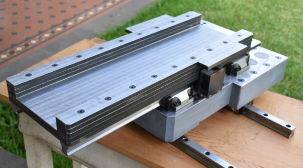
The typical machine tool you’ll find in a workshop has a base and frame made of cast iron or steel. These materials are chosen for their strength, robustness and their weight, which helps damp vibrations. However, it’s not the only way to make a machine tool. [John McNamara] has been working on a CNC mill with an epoxy base, with impressive results.

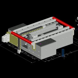
The molds were designed in CAD prior to casting, ensuring there was room for all required components.

The build is one that could be readily achieved in any decently equipped makerspace. [John] used lasercut steel parts to construct the molds for the epoxy base, with some custom turned parts as well. The precision cut parts fit together with great accuracy, and with proper control of the casting process there is minimal post-processing of the final cast piece required. The mold is built with zero draft angle, and is designed to be taken apart to remove the finished pieces. By using steel, the same mold can be used many times, though [John] notes that MDF could be used for a one-off build.

The base is cast in epoxy, mixed with granite aggregate and sand to create a strong, heavy, and vibration damping material. There are also steel reinforcements cast in place consisting of threaded rods, and conduits for various electrical connections. After casting, [John] has spent much time measuring and truing up the mill to ensure the best possible results from the outset.

It’s an impressive build, that shows that building your own accurate machine tools is quite achievable with the right tools and knowledge. We’ve seen similar work before, too – epoxy really does make a great material for casting at home.


This Force Controlled Robot Gripper Is Less Likely To Break Stuff

While robotic arms can handle a wide variety of tasks, the specific job at hand will have a major influence on the type of end effector used. For sorting ferromagnetic parts an electromagnet might be enough, while for more accurate location a mechanical gripper could be employed. If you’re working with particularly delicate objects or in concert with human beings, it may be desired to have a force controlled gripper to avoid damage. [James Bruton] has been whipping up a design of his own for just this purpose.

The basic gripper is 3D printed, with 3 fingers consisting of two joints each. Retraction of each finger is courtesy of bungee cord, while extension is via a servo attached to the finger through a spring. The position of each finger is measured with a resistive flex sensor. An Arduino Uno is employed to run the servos and read the attached sensors.

As force is applied by the servo, the spring begins to stretch. This leads to a greater difference between the servo position and the finger position as the applied force increases. By calculating this difference, it’s possible to determine the force applied by the fingers. This can then be used to limit the applied force of the gripper, to avoid breaking delicate objects or crushing soft, fleshy humans.

[James] notes that there are some drawbacks to the current design. The force required to move the fingers is inconsistent along their travel, and this interferes somewhat with accurate measurement. Overall though it’s a solid proof of concept and a good base for further revisions. Files are on Github for those who wish to tinker at home.

Being aware of the forces applied in mechanical settings can be key to getting good results. We’ve even seen arbor presses modified for just such a purpose. Video after the break.

Continue reading “This Force Controlled Robot Gripper Is Less Likely To Break Stuff” →

Building A Turbocharger Turbojet

Jet engines are known to be highly demanding machines, requiring the utmost attention to tolerances, material specifications, and operating regimes. If any of these parameters are ignored, failures can be catastrophic and expensive. Despite these exacting requirements, it is possible to build a jet engine in the home workshop – and using a turbocharger is a great way to do that. (Video also embedded after the break.)

[Tech Ingredients] does a great job of discussing the basic concepts behind the turbocharger jet engine build, and how various parameters impact performance and efficiency. Through the use of various rules of thumb, developed over years of experimentation by home builders and engineers alike, it’s possible to whip up a functioning engine without too much trial and error. The video breaks down and discusses the thermodynamics at play, as well as practical considerations like cooling and lubrication, in several easy to digest steps.

Jet engines are a popular high-octane build, and we’ve seen it pulled off before by makers like [Colin Furze]. The trick is to pull it off without causing yourself serious injury.

Continue reading “Building A Turbocharger Turbojet” →