Even More Firmware In Your Firmware

There are many ways to update an embedded system in the field. Images can fly through the air one a time, travel by sneaker or hitch a ride on other passing data. OK, maybe that’s a stretch, but there are certainly a plethora of ways to get those sweet update bytes into a target system. How are those bytes assembled, and what are the tools that do the assembly? This is the problem I needed to solve.

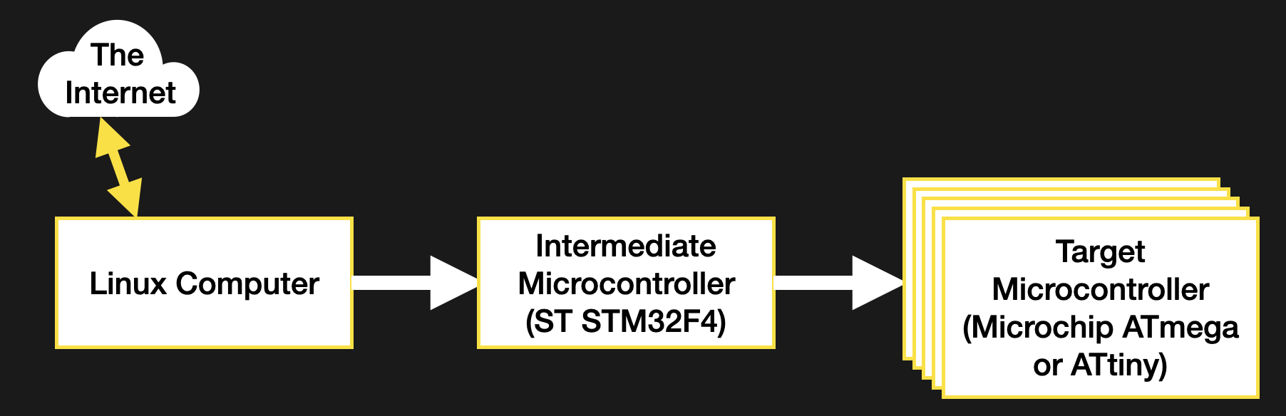
Recall, my system wasn’t a particularly novel one (see the block diagram below). Just a few computers asking each other for an update over some serial busses. I had chosen to bundle the payload firmware images into the binary for the intermediate microcontroller which was to carry out the update process. The additional constraint was that the blending of the three firmware images (one carrier and two payload) needed to happen long after compile time, on a different system with a separate toolchain. There were ultimately two options that fit the bill.

The system thirsty for an update

Continue reading “Even More Firmware In Your Firmware”

Raspberry Pi Helps Racer Master The Track

Looking to give himself a competitive edge, racer [Douglas Hedges] wanted to come up with a system that could give him real-time feedback on how his current performance compared to his previous fastest lap time. Armed with a Raspberry Pi and some Python libraries, he set out to add a simple telemetry system to his car. But as is often the case with these kind of projects, things just started snowballing from there.

The Raspberry Pi based data acquisition system.

At the most basic level, his system uses GPS position and speed information to light up a strip of RGB LEDs on the dashboard: green means he’s going faster than the previous best lap, and red means he isn’t. Any interface more complex than that would just be a distraction while he focuses on the track. But that doesn’t mean the Raspberry Pi can’t collect data for future review after the race is over.

With the basic functionality in place, [Douglas] turned his attention to collecting engine performance data. It turned out the car already had some pre-existing equipment for collecting metrics such as the air-fuel ratio and RPM, which he was able to connect to the Raspberry Pi thanks to its use of a well documented protocol. On top of that he added a Labjack U3 data acquisition system which let him pull in additional information like throttle position and coolant temperature. Grafana is used to visualize all of this data after the race, though it sounds like he’s also considering adding a cellular data connection vehicle data can be streamed out in real-time.

In the past we’ve seen onboard data collection systems make real-world races look more like their virtual counterparts, but it seems like the solution [Douglas] has come up with is more practical in the heat of the moment.

Continue reading “Raspberry Pi Helps Racer Master The Track”

Certifying Nuclear Reactors: How The NRC Approved Its First Small Modular Reactor Design

The US Nuclear Regulatory Commission (NRC) recently announced that it had approved certification of NuScale’s SMR (small modular reactor) design, completing its Phase 6 review of NuScale’s Design Certification Application (DCA). What this means is that SMRs using NuScale’s reactor design can legally be constructed within the US as soon as the rulemaking process completes. An NRC certification would also mean that certification of the design in other countries should pose no significant hurdles.

A question that remains unanswered at this point for most is how this certification process at the NRC actually works. Are there departments full of engineers at the NRC who have been twiddling their thumbs for the past decades while the US nuclear industry has been languishing? What was in the literally millions of documents that NuScale had to send to the NRC as part of the certification process, and what exactly are these six phases?

Stay tuned for a crash course in nuclear reactor certification, after a bit of SMR history.

Continue reading “Certifying Nuclear Reactors: How The NRC Approved Its First Small Modular Reactor Design”

3D Printed Video Terminal Dials C For Cyberpunk

Created for the Disobey 2020 hacker conference in Finland, thisĀ Blade Runner inspired communications terminal isn’t just for decoration. It was part of an interactive game that required attendees to physically connect their conference badges up and “call” different characters with the functional keypad on the front of the unit.

[Purkkaviritys] was in charge of designing the 3D printed enclosure for the device, which he says takes an entire 2 kg roll of filament to print out. Unfortunately he wasn’t as involved in the electronics side of things, so we don’t have a whole lot of information about the internals beyond the fact that its powered by a Raspberry Pi 4, features a HyperPixel 4.0 display, and uses power over Ethernet so it could be easily set up at the con with just a single cable run.

A look at the custom keypad PCB.

The keypad is a custom input device using the Arduino Micro and Cherry MX Blue switches with 3D printed keycaps to get that chunky payphone look and feel. [Purkkaviritys] mentions that the keypad is also responsible for controlling the RGB LED strips built into the sides of the terminal, and that the Raspberry Pi toggles the status of the Caps, Scroll Lock, and Num Lock keys to select the different lighting patterns.

Naturally we’d like to see more info on how this beauty was put together, but given that it was built for such a specific purpose, it’s not like you’d really need to duplicate the original configuration anyway. Thanks to [Purkkaviritys] you have the STL files to print off our own copy of the gloriously cyberpunk enclosure, all you’ve got to do now is figure out how to make video calls with it.

Continue reading “3D Printed Video Terminal Dials C For Cyberpunk”

Pulse Generator Does The Job With An STM8

When working with hardware, whether a repair or a fresh build, it’s often necessary to test something. Depending on what you’re working with, this can be easy or a total pain if you can’t get the right signal to the right place. To eliminate this frustrating problem, [WilkoL] built a useful pulse generator for use in the lab.

[WilkoL] notes that historically, the job of generating pulses of varying length and frequency would be achieved with a smattering of 555 timers. While this is a perfectly cromulent way to do so, it was desired to take a different approach for the added flexibility modern hardware can offer. The pulse generator is instead built around an STM8 microcontroller; an unusual choice in this era, to be sure. [WilkoL] specified the part for its incredibly low cost, and highly capable timer hardware – perfect for the job.

Combined with an ST7735 TFT LCD screen, and programmed in bare metal for efficiency’s sake, the final project is installed in a project box with controls for frequency and pulse length – no more, no less. Capable of pulse lengths from 250 ns to 90 s, and frequencies from 10 mHz to 2 MHz, it’s a tool that should be comfortable testing everything from servos to mechanical counters.

Of course, if you need to get down to picosecond timescales, an avalanche pulse generator might be more your speed. Video after the break.

Continue reading “Pulse Generator Does The Job With An STM8”

ESP32 Becomes Modern Controller For A 1960s Clock

These days, everything’s got a clock in it, and a good proportion of those clocks are automatically syncronized to high-accuracy Internet time servers. Back in the past, things weren’t so easy. Often, institutions that required accurate time would use a single highly-accurate primary clock to drive a series of secondary clocks around a facility. Without the primary clock, the secondary clock has no signal to drive it. [Oleksii Samorukov] had just such a clock, and whipped up a controller to stand in for timekeeping duty.

The secondary clock in question is a Pragotron PJ 27, which requires regular 12V signals of alternating polarity in order to keep time. To handle this job, [Oleksii] decided to use an ESP32 in combination with an L298N motor controller. The L298N is an H-bridge driver chip, allowing it to easily supply the 12V signals in alternating polarities where required. To ensure the system keeps accurate time, the ESP32 regularly queries an NTP time server over WiFi.

It’s a tidy build, and one that brings this attractive 1960s timepiece into the modern era. We’d love to have such a stylish, well-built clock in our own home, too. Of course, if you want really accurate time, building a GPS clock is a great option, too!

[Thanks to Irregular Shed for the tip!]

KiwiSDR Vs RaspberrySDR — A Tale Of Two SDRs

Once you move away from the usual software defined radio (SDR) dongles, you have only a few choices unless you want to drop some serious cash. One common hobby-grade SDR is the KiwiSDR. This popular unit runs Linux and can receive up to 30 MHz. The platform uses a dedicated A/D converter, an FPGA, and BeagleBone computer. Success of course breeds imitators, and especially when you have an open source design like the Kiwi, you are going to find similar devices with possibly different end goals. That’s how the RaspberrySDR came to be. This is a very similar unit to the KiwiSDR but it uses a Raspberry Pi, along with a handful of other differences. What’s different? [KA7OEI] tells us in a recent blog post.

Other than the obvious difference of the computer and all that it entails, the RaspberrySDR has a higher speed A/D (125 MHz vs 66 MHz) and 16-bits of resolution instead of the Kiwi’s 14 bits. This combines to give the Raspberry a wider receive range (up to 60 MHz) and — in theory — better performance in terms of dynamic range and distortion.

Continue reading “KiwiSDR Vs RaspberrySDR — A Tale Of Two SDRs”