Mills are a huge investment, and for hobbyists without the space to install their own personal mill, it can sometimes be a pain to have to find a facility with a mill to complete your project.
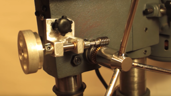
What if you could convert your drill press into a mill instead? YouTuber [Small Metalworking Machines] explores this in his video, where he takes a small Central Machinery drill press and adds a few mods. He took some steps to improve the quill, spindle, and bearings — boring down the quill, replacing the bearings, and finally turning and re-threading the spindle it at 1/2-20.
With the adjustments, he was able to add in a cheap drill chuck, which fit in quite nicely with just a slight wobble of 5 thousandths on either side. To introduce some control, he added in a worm gear to engage a gear on the spindle. A pivot point disengages the worm gear, while bearings provide it controlled movement from the worm wheel.
He also added a cheap milling table from eBay, attached to the base of the drill press, all for a total of $120. While it’s not perfect, it’s still significantly less expensive than buying a mill!
Small hobby aircraft and light plastic parts go hand in hand, and a 3D printing pen makes lightweight plastic things without the overhead of CAD work and running a 3D printer. So could a 3D pen create useful plastic bits for small quadcopters? [Michael Niggel] decided to find out by building his drone parts with a 3D pen loaded with ABS plastic. He mostly discovered that the created objects could politely be said to look like they were sketched by a toddler, but that’s not all he learned.
He found that in general creating an object was harder than the marketing materials implied. As soon as the filament exits the pen’s nozzle, the thin little molten line of plastic cools rapidly and does two things: it has a tendency to curl, and loses its desire to stick to things. [Michael] found the whole affair worked much less like ‘drawing in thin air’ and rather more like piping frosting, or caulking.
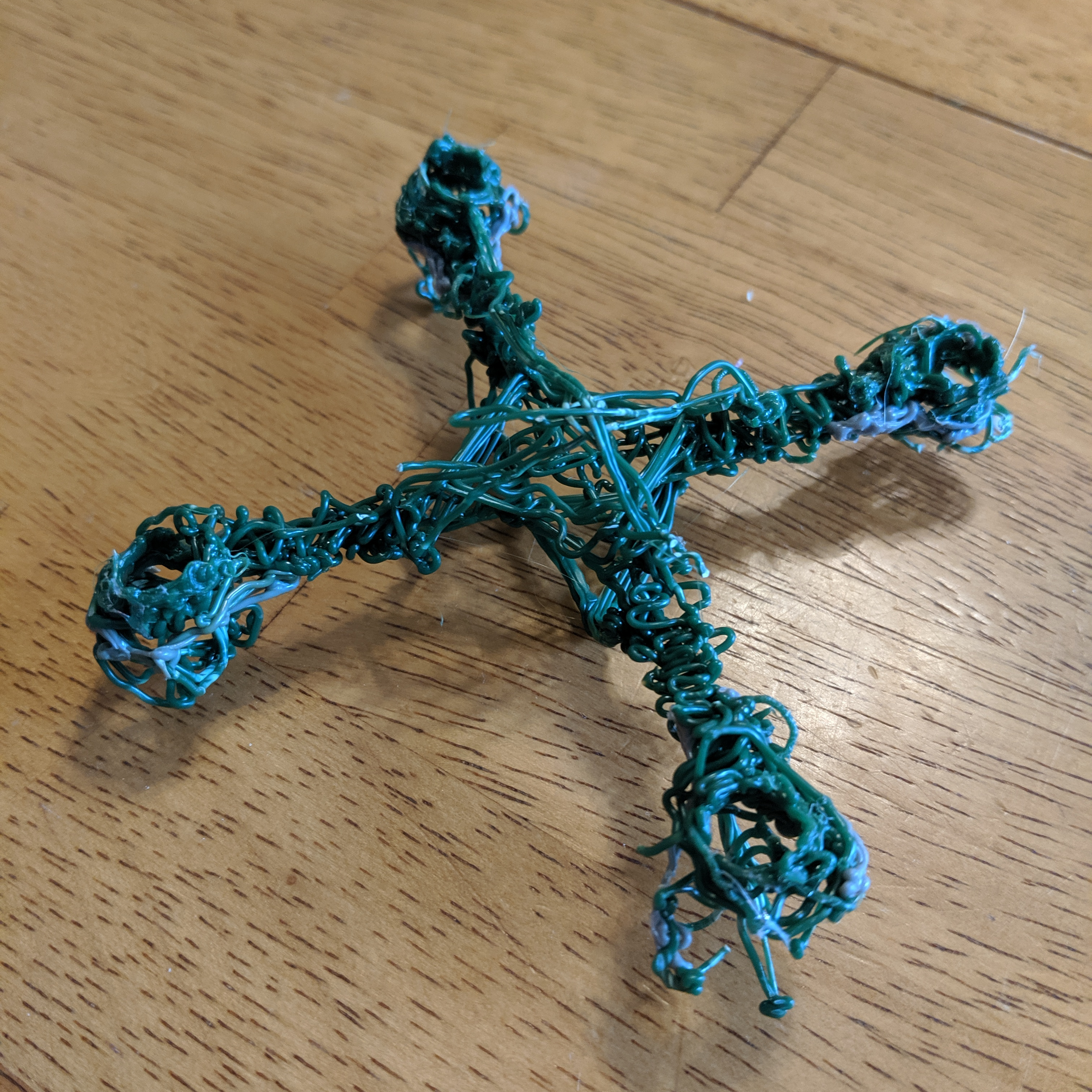
An almost functional micro quad frame. The arms aren’t rigid enough to hold the motors vertical when under power.
Nevertheless, [Michael] sought to discover whether a 3D pen could be used to make quick and dirty parts of any use. He created two antenna brackets and one micro quad frame. All three are chaotic messes, but one antenna bracket was perfectly serviceable. The 3D pen was indeed able to create a strangely-shaped part that would have been a nightmare to CAD up. The other antenna part worked, but didn’t do anything a zip tie wouldn’t have done better. The rapid cooling of the plastic from the 3D pen has an advantage: extrusions don’t “droop” like a glob of hot glue does before it hardens.
By now, [Michael] agreed that the best way to create a plastic part of any complexity whatsoever seemed to be to draw sections flat, build them up in layers, then use the pen to weld the pieces together and add bulk. The micro quad frame he made in this way doesn’t look any nicer than the other attempts, but it did hold the parts correctly. Sadly, it would not fly. Once the motors powered up, the arms would twist and the flight controller was unable to compensate for motors that wouldn’t stay straight. This could probably be overcome, but while the end result was dirty it certainly wasn’t quick. The 3D pen’s niche seems restricted to simple, unstressed parts that aren’t permitted to gaze up themselves in a mirror.
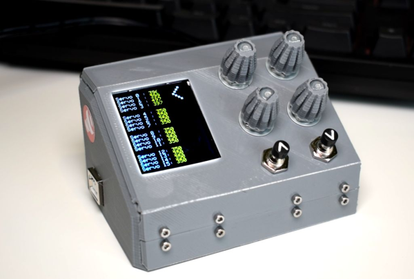
You know how it goes — sometimes you just have to stop in the middle of a project and build yourself a tool that vastly improves your workflow as soon as it’s completed. [Ikkalebob] aka [Will Cogley] on YouTube is working on some super secret project that requires a whole bunch of servos. And since all of them have to be tested and set, he built this adorable servo tester as a time-saving gift to himself.
This tester revolves around an Adafruit 16-channel servo driver and an Arduino Uno. The servos show up on the screen in groups of four, and can be tested four at a time with the pots. The buttons let [Ikkalebob] move up and down between the groups. The SainSmart LCD proved to be more difficult to set up than others, but [Ikkalebob] did you a solid and tweaked the library. It’s available along with his code and STLs.
Speaking of STLs, we really dig the mini NASA console look and the folding enclosure. Leveraging the print process to build hinges and other things is awesome, and so is getting away with using fewer fasteners. You can see a bit of how [Ikkalebob] designed it in the video after the break.
They say that in order to understand recursion, you must first understand recursion. Once you master that concept, you might decide that it’s time to write your own compiler that can compile itself as a fun side project. According to [Warren] aka [DoctorWkt], who documented every step of writing this C compiler from scratch, a true compiler will be able to do that.
Some of the goals for the project included self-compiling, focusing on a real hardware platform, practicality, and simplicity. [Warren] outlines a lot of the theory of compilers as well, including all the lexical, grammar, and semantic analysis and then the final translation into assembly language, but really focuses on making this compiler one for practical use rather than just a theoretical implementation. He focuses on Intel x86-64 and 32-bit ARM platforms too, which are widely available.
This project is a long read and very thoroughly documented at around 100,000 words, so if you’ve ever been interested in compilers this is a great place to start. There are a lot of other great compiler tools floating around too, like the Compiler Explorer which shows you generated code as you write in a higher level language.
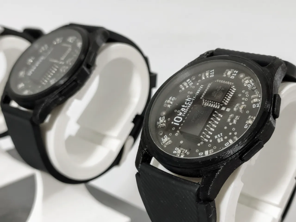
When you read “Arduino wristwatch”, you fall into the trap of envisioning an Arduino UNO clumsily strapped to someone’s wrist. [Marijo Blažević’s] creation is much more polished than that. A round circuit board holds two surface mount ICs and 12 LEDs. The whole thing looks nice fit snugly inside of a watch body. It isn’t a Rolex, but it does have considerable geek cred without being unwearable in polite company.
One IC is an AVR micro, of course. The other is a DS3231 real time clock with built-in crystal. A CR2032 keeps it all running. The main body, the outer ring, the bottom, and the buttons are 3D printed in PLA. The crystal and the band are the only mechanical parts not printed. The bill of materials shows a 36mm crystal and even provides links for all the parts.
You don’t want to run LEDs all the time because it is bad on the battery. When you press the button once, you get one of the LEDs to light to show the hours. Another press reads the minutes in units of 5 minutes. A third press shows you one of five LEDs to show how many minutes to add. For example, if the time is 9:26 you’d get LED 9 (hours), LED 5 for 25 minutes, and the third press would show LED 1 for 1 extra minute. If either of the minute indicators show 12 o’clock, that indicates zero minutes.
The exciting thing, of course, is that you can program it beyond the code on GitHub. Already it can tell time and display the temperature. You don’t have a lot of I/O, but you ought to be able to get some more options and maybe some flashy LED blinking patterns in if you try.
It’s the [Bruce Land]-iest season of all, when the Cornell professor submits the projects his microcontroller class students have been working on all semester. Imagination does not seem to be in short supply with these students, and we always look forward to these tips this time of year.
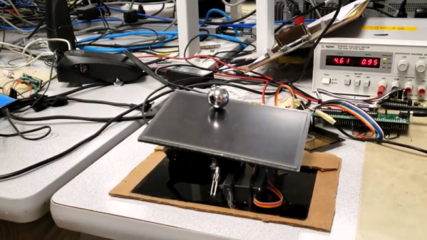
[Greg] and [Sam]’s touch-screen two-dimensional ball balancer is a good example of what [Land]’s students turn out. The resistive touch screen is supported by a 3D-printed gimballed platform and tilted in two axes by hobby servos. [Greg] and [Sam] chose to read the voltage outputs from the touch screen directly using the ADC on a PIC32, toggling between the two axes at 2 kHz. Two PID control loops were implemented to keep the ball as centered as possible on the platform, and the video below shows that there’s still some loop tuning to do. But given the positional inaccuracies of hobby servos and the compliance in the gimbal, we’re impressed that they were able to keep the system under control at all.
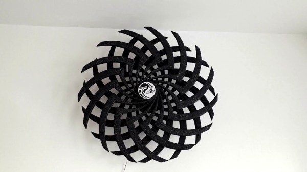
Moiré illusions can be visually captivating, particularly when a little rotational motion is thrown in the mix. [Dushyant Ahuja] was a fan of these moving Moiré sculptures he’d seen around the place, and decided to create his own.
The build is based around spinning two spoked discs in opposite directions, such that the spokes create moving Moiré patterns as they turn. To achieve this, the discs were 3D printed, along with a central housing containing two 12 volt gear motors. 3D printed gears are used to allow both discs to rotate about the same axis. Nominally, the motors spin relatively slowly, generating a pleasing, hypnotic effect when turning the discs.
The drivetrain is under the control of an ESP8266, though [Dushyant] notes that to get the basic effect, one need only connect the motors to a 12 volt power supply and let them run. However, future plans involve adding some LEDs for bling, and varying the motor speed to create yet more complex effects. With the microcontroller already installed, upgrades should be a cinch.