More than a few hackers have put in the considerable time and effort required to build a rover inspired by NASA’s robotic Martian explorers, but unfortunately even the most well funded home tinkerer can’t afford the ticket to send their creation offworld. So most of these builds don’t journey through anything more exciting than a backyard sandbox. Not that we can blame their creators, we think a homebrew rover will look just as cool in your living room as it would traipsing through a rock quarry.
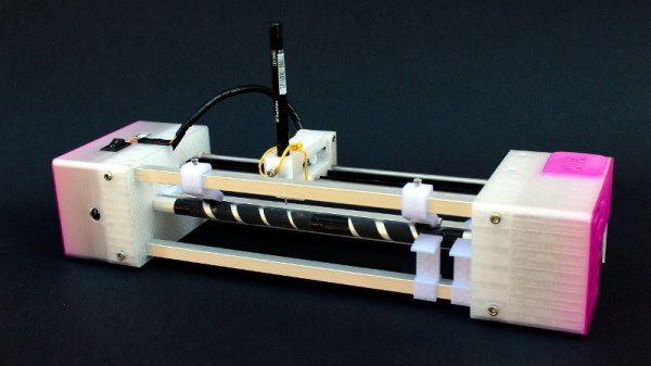
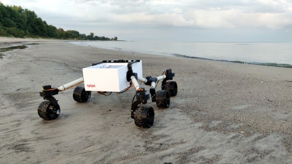
 But the DIY rover status quo clearly wasn’t sufficient for [Jakob Krantz], who decided the best way to test his new Curiosity-inspired rover was to let it frolic around on the beach for an afternoon. But judging by the video after the break, his beefy 3D printed bot proved to be more than up to the task; powering through wildly uneven terrain with little difficulty.
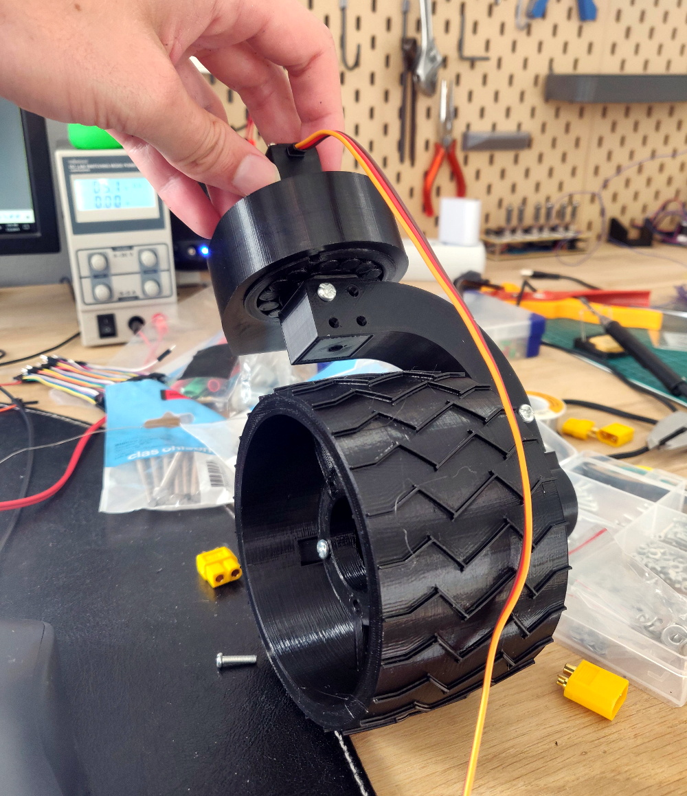
Beyond a few “real” bearings here and there, all of the key components for the rover are 3D printed. [Jakob] did borrow a couple existing designs, like a printable bearing he found on Thingiverse, but for the most part he’s been toiling away at the design in Fusion 360 and using images of the real Curiosity rover as his guide.
Right now, he’s controlling the rover with a standard 6 channel RC receiver. Four channels are mapped to the steering servos, and a fifth to the single electronic speed control that commands the six wheel motors. But he’s recently added an Arduino to the rover which will eventually be in charge of interpreting the RC commands. This will allow more complex maneuvers with fewer channels, such as the ability to rotate in place.
We’re proud to count our very own [Roger Cheng] among the rover wrangling hackers of the world. An entire community has sprung up around his six-wheeled Sawppy, and the knowledge gained during its design and construction could be applicable to any number of other projects.
Continue reading “3D Printed Rover Enjoys Long Walks On The Beach”