Refurbishing A Classic Electrostatic Speaker PSU

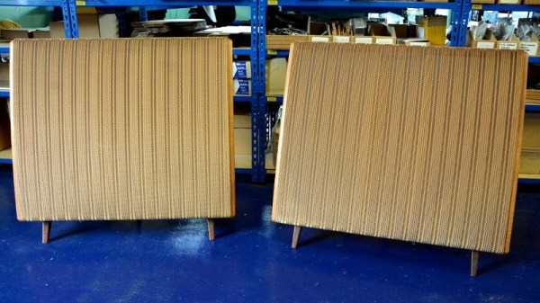
Sometimes a project takes longer than it should to land in the Hackaday in-tray, but when we read about it there’s such gold to be found that it’s worth sharing with you our readers despite its slight lack of freshness. So it is with [Andrew Back]’s refurbishment of his Quad electrostatic speaker system power supply, it may have been published back in August but the glimpse it gives us into these legendary audio components is fascinating.

The inner workings of an electrostatic loudspeaker

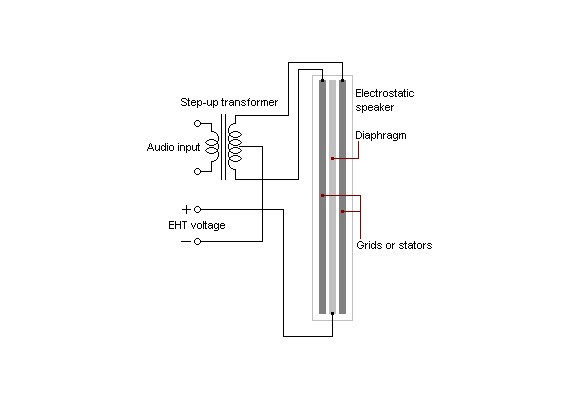
An electrostatic speaker is in effect a capacitor with a very large surface area, of which one plate is a flexible membrane suspended between two pieces of acoustically transparent mesh that form the other plates. A very high DC bias voltage in the multiple kilovolts region is applied across the capacitor, and the audio is superimposed upon it at a peak-to-peak voltage of somewhere under a kilovolt through a step-up transformer from the audio amplifier. There are some refinements such as that the audio is fed as a push-pull signal to the opposing mesh plates and that there are bass and treble panels with different thickness membranes, but these speakers are otherwise surprisingly simple devices.

The problem with [Andrew]’s speakers became apparent when he took a high voltage probe to them, one speaker delivered 3 kV from its power supply while the other delivered only 1 kV. Each supply took the form of a mains transformer and a voltage multiplier board, so from there it became a case of replacing the aged diodes and capacitors with modern equivalents before applying an insulating layer for safety.

Electrostatic speakers are no stranger to Hackaday, we’ve taken an in-depth look at them in the past. You may also find some of our colleague [Steven Dufresne]’s writing on the matter to be of interest, on measuring high voltages, and his experience wrangling high voltage.

Get Your Tweets Without Looking

Head-mounted displays range from cumbersome to glass-hole-ish. Smart watches have their niche, but they still take your eyes away from whatever you are doing, like driving. Voice assistants can read to you, but they require a speaker that everyone else in the car has to listen to, or a headset that blocks out important sound. Ignoring incoming messages is out of the question so the answer may be to use a different sense than vision. A joint project between Facebook Inc. and the Massachusetts Institute of Technology have a solution which uses the somatosensory reception of your forearm.

A similar idea came across our desk years ago and seemed promising, but it is hard to sell something that is more difficult than the current technique, even if it is advantageous in the long run. In 2013, a wearer had his or her back covered in vibrator motors, and it acted like the haptic version of a spectrum analyzer. Now, the vibrators have been reduced in number to fit under a sleeve by utilizing patterns. It is being developed for people with hearing or vision impairment but what drivers aren’t impaired while looking at their phones?

Patterns are what really set this version apart. Rather than relaying a discrete note on a finger, or a range of values across the back, the 39 English phenomes are given a unique sequence of vibrations which is enough to encode any word. A phenome phoneme is the smallest distinct unit of speech. The video below shows how those phonemes are translated to haptic feedback. Hopefully, we can send tweets without using our hands or mouths to upgrade to complete telepathy.

Continue reading “Get Your Tweets Without Looking”

Clever Wedges That Will Increase Your PCB Assembly Yield

If there’s one thing that will bring down the yield of your PCB assembly, it’s your solder paste. Put too much on, and you’ll get bridged leads. If you don’t put enough on, that pad might not make good contact. [ScalarElectric] has an amazing trick that’s sure to astonish and astound. Just use wedges and you’ll get better yield with fine-pitched components.

The trick here is to define the cream/solder paste layer of each package as a wedge on each pad instead of the usual rectangle. This gives a few benefits, the largest being the increased gap between paste shapes. You’re also getting a reduction in the total amount of paste applied, and a subsequent improvement in yield. (Reportedly, we’d love to see some data on this.)

PCB design tools usually have a way to alter the size of the cream/solder paste layer of a design, and indeed one option is to simply shrink the size of the paste layer elements. The trick to the wedges is increasing the total distance between solderpaste blobs while keeping the total amount of solderpaste high. This technique can be used down to 0.5mm pitch parts, and everything works like a charm.

While this is a little outside of our wheelhouse here at Hackaday — it is, after all, a novel use of existing tools that is mostly applicable to electronic design and production. [Ed Note: Sarcasm.] You can check out a few pics of this technique in the slideshow below. If you test this technique out, be sure to let us know how it went!

Experiment With Lumia, The Cheap And Easy Way

Light is a wonderful medium for art, and there’s all manner of ways to approach it. We’ve always been huge fans of all that blinks and glows, but there’s a whole wide world of other methods and techniques in the lighting arena. Lumia is one that does not always get a lot of mainstream attention, and so [Adam Raugh] has created this video, sharing both the history of the effect, and various ways to create it yourself. 

Lumia was once used to refer to a broad swathe of artistic lighting, but these days, more commonly refers to effects that create an aurora-like appearance, as one would see near the poles of our fine Earth. [Adam] first covers the history of the effect, as pioneered by Thomas Wilfred with the Clavilux in the early part of the 20th Century.

The video then covers the basics of creating lumia effects using DIY methods. The key is to combine slow rotation with an organically deformed refractive medium. [Adam]’s rig of choice is a basic laser projector, rotating at just 1/3 of a rotation per minute. This is then combined with a variety of homebrewed refractive media – torture tubes made from glass, acrylic sheets coated with muddled epoxy, and even a crumpled water bottle.

It’s an excellent primer on how to get started with lumia, and [Adam] covers a wide variety of tips and tricks as well as potential pitfalls to avoid.

We see plenty of great lighting projects around these parts – check out the Kinetic Chandelier. Video after the break.

Continue reading “Experiment With Lumia, The Cheap And Easy Way”

Game Boy Camera – Now In Color

The Game Boy Camera is a legendary piece of 90s gaming hardware, despite not being a game at all. It consisted of a low-resolution greyscale camera, fitted to a Game Boy cartridge, that you could use to photograph your friends, vandalise their pictures, then print them out on a thermal printer. It’s hardware that was fun because of its limitations, not despite them. However, [Matt] wondered if there was a way to use early photographic techniques to get color photos.

The technique is simple – get red, green, and blue filters, and take three photos – one using each filter. Then, combine the photos digitally to create the color image.  This necessitates an amusingly complex process to transfer the photos from Game Boy to PC, of course.

There are some limitations – due to the speed of the Game Boy Camera, it works best with static scenes, as it takes several seconds to shoot. Also, due to the low resolution, it’s best to choose subjects with broad swathes of color. Despite this, [Matt] managed to take some great images with a colorful yet vintage digital charm. There’s other ways to achieve this, of course – like bringing the power of neural networks to bear on your low-res Game Boy images. Video after the break.

Continue reading “Game Boy Camera – Now In Color”

FPGA Emulates A PDP-1, Breathes New Life Into Classic Video Game

If you’ve ever wanted to sit at the console of the machine that started the revolution in interactive computing, your options are extremely limited. Of the 53 PDP-1 machines that Digital Equipment Corporation made, only three are known to still exist, and just one machine is still in working order at the Computer History Museum. So a rousing game of Spacewar! on the original hardware is probably not something to put on your bucket list.

But thanks to [Hrvoje], there’s now an FPGA emulation of the PDP-1 that lets you play the granddaddy of all video games without breaking into the CHM. The project was started simply to give [Hrvoje] a sandbox for learning FPGAs and Verilog, but apparently went much further than that. The emulation features the complete PDP-1 instruction set, 4kB of core memory, and representations of the original paper tape reader, teletype, operator’s console, and the classic Type 30 CRT. All the hardware is displayed on a standard HDMI monitor, but it’s the CRT implementation that really sells this. The original Type 30 monitor used a CRT from a radar set, and had long-persistence phosphors that gave the display a very distinctive look. [Hrvoje] replicated that by storing each pixel as three values (X, Y, and brightness) in a circle of four chained shift registers. As the pixels move through the shift registers, the brightness value is decreased so it slowly fades. [Hrvoje] thinks it doesn’t look quite right, but we’ll respectfully disagree on that point.

We’ve argued before that the PDP-1 is the machine that started hacker culture, and we think this project is a fitting tribute to the machine as we enter the year in which it will turn sixty. Having the chance to play with it through this emulation is just icing on its birthday cake.

Continue reading “FPGA Emulates A PDP-1, Breathes New Life Into Classic Video Game”

Explaining Fourier Again

One of the nice things about living in the Internet age is that creating amazing simulations and animations is relatively simple today. [SmarterEveryDay] recently did a video that shows this off, discussing a blog post (which was in Turkish) to show how sine waves can add together to create arbitrary waveforms. You can see the English video, below.

We’ve seen similar things before, but if you haven’t you can really see how a point on a moving circle describes a sine wave. Through adding those waves, anything can then be done.

Continue reading “Explaining Fourier Again”