Microcontroller And IMU Team Up For Simple Flight Sim Controls

Classes are over at Cornell, and that means one thing: the students in [Bruce Land]’s microcontroller design course have submitted their final projects, many of which, like this flight control system for Google Earth’s flight simulator, find their way to the Hackaday tips line.

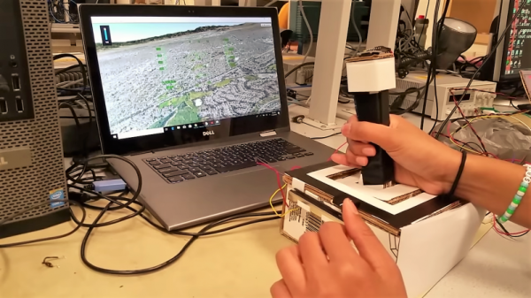
We actually got this tip several days ago, but since it revealed to us the previously unknown fact that Google Earth has a flight simulator mode, we’ve been somewhat distracted. Normally controlled by mouse and keyboard, [Sheila Balu] decided to give the sim a full set of flight controls to make it more realistic. The controls consist of a joystick with throttle, rudder pedals, and a small control panel with random switches. The whole thing is built of cardboard to keep costs down and to make the system easy to replicate. Interestingly, the joystick does not have the usual gimbals-mounted potentiometers to detect pitch and roll; rather, an IMU mounted on the top of the stick provides data on the stick position. All the controls talk to a PIC32, which sends the inputs over a serial cable to a Python script on the PC running Google Earth; the script simulates the mouse and keyboard commands needed to fly the sim. The video below shows [Sheila] taking an F-16 out for a spin, but despite being a pilot herself since age 16, she was curiously unable to land the fighter jet safely in a suburban neighborhood.

[Bruce]’s course looks like a blast, and [Sheila] clearly enjoyed it. We’re looking forward to the project dump, which last year included this billy-goat balancing Stewart platform, and a robotic ice cream topping applicator.

Continue reading “Microcontroller And IMU Team Up For Simple Flight Sim Controls”

A Perfectly Orderly Way To Manage Your Time

[Paul Gallagher] has spent years separating his tasks into carefully measured out blocks, a method of time management known as the Pomodoro Technique. If that’s not enough proof that he’s considerably more organized and structured than the average hacker, you only need to take a look at this gorgeous Pomodoro Timer he’s entered into the Circuit Sculpture Contest. Just don’t be surprised if you suddenly feel like your own time management skills aren’t cutting it.

While [Paul] has traditionally just kept mental note of the hour-long blocks of time he breaks his work into, he thought it was about time he put together a dedicated timer to make sure he’s running on schedule. Of course he could have used a commercially available timer or an application on his phone, but he wanted to make something that was simple and didn’t cause any distractions. A timer that was easy to start, reliable, and didn’t do anything extraneous. We’re not sure if looking like the product of a more advanced civilization was part of his official list of goals, but he managed to achieve it in any event.

The timer is broken up into two principle parts: the lower section which has the controls, USB port, a handful of passive components, and an ATmega328 microcontroller, and the top section which makes up the three digit LED display. The two sections are connected by a header on the rear side which makes it easy for [Paul] to take the timer apart if he needs to get back into it for any reason. Notably absent in the design is a RTC; the relatively short duration of the timer (up to a maximum of 95 minutes) means the ATmega328 can be trusted to keep track of the elapsed time itself with an acceptable amount of drift.

The display side of the timer is really a sight to behold, with the legs of each LED soldered to a pair of carefully bent copper wires so they match the angle of the front panel. The associated resistors have been artfully snipped so that their bodies sit flat on the PCB while their leads reach out to the perfect length. It looks like a maintenance nightmare in there, but we love it anyway.

As we near the half-way mark of the Circuit Sculpture Contest, there’s still plenty of time to submit your own piece of functional art. If you’ve got a project that eschews the printed circuit board for a chance to bare it all, write it up on Hackaday.io and be sure to send it in before the January 8th, 2019 deadline.

Continue reading “A Perfectly Orderly Way To Manage Your Time”

Epoxy Too Thin? Use Wood Flour As A Thixotropic Filler

The world of glues is wide and varied, and it pays to use the right glue for the job. When [Eric] needed to stick a wide and flat 3D printed mount onto the back of a PCB that had been weatherproofed with an uneven epoxy coating, he needed a gap-filling adhesive that would bond to both surfaces. It seemed like a job for the hot glue gun, but the surface was a bit larger than [Eric] was comfortable using with hot glue for. The larger the surface to be glued, the harder it is to do the whole thing before hot glue cools too much to bond properly.

What [Eric] really wanted to use was a high quality two-part epoxy that he already had on hand, but the stuff was too runny to work properly for this application. His solution was to thicken it with a thixotropic filler, which yields a mixture that is akin to peanut butter: sticky, easily spread to where it’s needed, but otherwise stays in place without dripping or sagging and doesn’t affect bonding.

3D printed pad stuck to back of PCB with thickened epoxy.

Common thixotropic fillers include ground silica or plastic fibers, but [Eric]’s choice was wood flour. Wood flour is really just very fine sawdust, and easily obtained from the bag on his orbital sander. Simply mix up a batch of thin two-part epoxy and stir in some wood flour until the sticky mixture holds its shape. Apply as needed, and allow it to cure.

Thanks to this, [Eric] was able to securely glue a 3D printed pad to the back of his animated LED snowflakes to help mount them in tricky spots. Whether for small projects or huge installations, LEDs, PCBs, and snowflakes are a good combination.

Nintendo Does Sony, Better Than Sony

Fans of game consoles from the golden era of TV game appliances have been in for a treat over the past couple of years as a slew of official reboots of the stars of the past have reached the market. These so-called “classic” consoles closely follow the styling of the originals, but under the hood they pack modern hardware running an emulator to play a selection of games from ROM. Even better, with a bit of hacking they can run more than just the supplied emulator, people have managed to use them to emulate completely different consoles. Even then, it’s unexpected to find that a PlayStation emulator on a Super Nintendo Classic runs PlayStation games better than the same emulator built in to Sony’s own PlayStation Classic console.

The feat from [8 Bit Flashback] is achieved despite both machines having near-identical hardware specifications based upon the Allwinner R16 system-on-chip. The Nintendo provides smoother action and more responsive controls, making for a far superior gaming experience. How is this achieved? The most significant difference is that the SNES Classic had the RetroArch front end installed upon it, which may have lent some optimisations and tweaks to make the system more efficient.

Readers with an eye for unusual consoles may remember another Nintendo/Sony hybrid, the ill-fated early-1990s prototype SNES with a CD-ROM which was the first machine to bear the name “PlayStation” (or “Play Station” as it was sometimes styled, leading Sony marketeers to be hot on writers using a space between the words a few years later).

Continue reading “Nintendo Does Sony, Better Than Sony”

Sanding Seashells By The Seashore

We all maintain this balancing act between the cool things we want, the money we can spend, and our free time. When the pièce de résistance is a couple of orders of magnitude out of our budget, the only question is, “Do I want to spend the time to build my own?” [Nick Charlton] clearly answered “Yes,” and documented the process for his Nautilus speakers. The speaker design was inspired by Bowers & Wilkins and revised from a previous Thingiverse model which is credited.

The sound or acoustic modeling is not what we want to focus on since the original looks like something out of a sci-fi parody. We want to talk about the smart finishing touches that transform a couple of 3D printed shells into enviable centerpieces. The first, and most apparent is the surface. 3D prints from consumer FDM printers are prone to layer lines, and that aesthetic has ceased to be trendy. Textured paint will cover them nicely and requires minimal elbow grease. Besides sand and shells go together naturally. At first glance, the tripod legs holding these speakers seemed like a classy purchase from an upscale furniture store, but they are, in fact, stained wood and ground-down bolts. Nicely done.

The moral is to work smarter, take pictures, then drop us a line.

Old Game Development IDE Goes FPGA

If you have a thing for old game development — things like the Atari 2600 or similar period arcade games — you might already know about the 8bitworkshop IDE. There you can develop code in your browser for those platforms. In a recent blog post, the site announced you can now also do FPGA development in the IDE.

According to the site:

Most computers are fast enough to render a game at 60 Hz, which requires simulating Verilog at almost 5 million ticks per second.

To activate Verilog, you need to select the hamburger menu to the top left, select Platform, and then under Hardware, check Verilog. What makes this different from, say, EDA Playground, is that the output can be waveforms or the output to a virtual TV monitor. For example, here’s one of the examples:

The Verilog code is generating horizontal and vertical sync along with an RGB output and the results appear on the monitor to the right. There is a handle at the bottom of the screen. If you drag it up you will see the logic analyzer output. Drag it down and you’ll see the screen again. The examples include an 8-bit and 16-bit CPU, and example games that can even read the mouse.

Honestly, we don’t think anyone would suggest using Verilog to write in-browser games. That isn’t really the point here. However, if you are trying to learn Verilog, it is great fun to be able to produce something other than just abstract waveforms from simulation. The only downside is that to move to a real piece of hardware, you’d need to duplicate the interfaces provided by the IDE. That would not be very hard, and — of course — if you are just using it to learn you can try a different project for the real world.

If you need help getting going in Verilog, we have a series of boot camps that can help. Those tutorials use EDA Playground, but they’d probably work here, too. If you try them in the IDE, be sure to let us know your experience.

Refurbishing A Classic Electrostatic Speaker PSU

Sometimes a project takes longer than it should to land in the Hackaday in-tray, but when we read about it there’s such gold to be found that it’s worth sharing with you our readers despite its slight lack of freshness. So it is with [Andrew Back]’s refurbishment of his Quad electrostatic speaker system power supply, it may have been published back in August but the glimpse it gives us into these legendary audio components is fascinating.

The inner workings of an electrostatic loudspeaker

An electrostatic speaker is in effect a capacitor with a very large surface area, of which one plate is a flexible membrane suspended between two pieces of acoustically transparent mesh that form the other plates. A very high DC bias voltage in the multiple kilovolts region is applied across the capacitor, and the audio is superimposed upon it at a peak-to-peak voltage of somewhere under a kilovolt through a step-up transformer from the audio amplifier. There are some refinements such as that the audio is fed as a push-pull signal to the opposing mesh plates and that there are bass and treble panels with different thickness membranes, but these speakers are otherwise surprisingly simple devices.

The problem with [Andrew]’s speakers became apparent when he took a high voltage probe to them, one speaker delivered 3 kV from its power supply while the other delivered only 1 kV. Each supply took the form of a mains transformer and a voltage multiplier board, so from there it became a case of replacing the aged diodes and capacitors with modern equivalents before applying an insulating layer for safety.

Electrostatic speakers are no stranger to Hackaday, we’ve taken an in-depth look at them in the past. You may also find some of our colleague [Steven Dufresne]’s writing on the matter to be of interest, on measuring high voltages, and his experience wrangling high voltage.