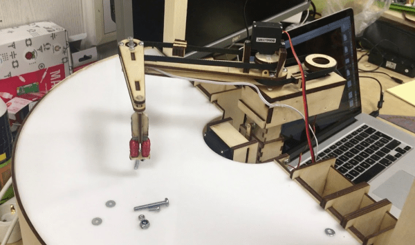
Fail Of The Week: Two Rotors Are Not Better Than Four

Fair warning: [Paweł Spychalski]’s video is mostly him talking about how bad his “dualcopter” ended up. There are a few sequences of the ill-fated UAV undergoing flight tests, most of which seem to end with it doing a reasonable impression of a post-hole auger. We have to admit that it’s a pretty poor drone. But one can only truly fail if one fails to have some fun doing it, [Paweł] enjoyed considerable success, at least judging by the glee with which he repeatedly cratered the craft.

The overall idea seems to make sense, with coaxial props mounted in the middle of a circular 3D-printed frame. Mounted below the props are crossed vanes controlled by two servos. The vanes sit in the rotor wash and provide pitch and roll control, while yaw and thrust are controlled by varying the speeds of the counter-rotating props. [Paweł] knew going in that this was a sketchy aerodynamic design, and was surprised it performed as well as it did. But with ground effects limiting roll and pitch control close to the ground, the less-than-adequate thrust due to turbulence between the rotors, and the tendency for the center of mass and the center of gravity to get out whack with each other, all made for a joyously unstable and difficult to control aircraft.

Despite the poor performance, [Paweł] has plans for a Mark II dualrotor, a smaller craft with some changes based on what he learned. He’s no slouch at pushing the limits with multirotors, with 3D-printed racing quad frames and using LoRa for control beyond visual range. Still, we’re sure he’d appreciate constructive criticism in the comments, and we wish him luck with the next one.

Continue reading “Fail Of The Week: Two Rotors Are Not Better Than Four”

555 Ways To Speed Control A DC Motor

The 555 timer IC is a handful of active components all baked into one beautifully useful 8 pin package. Originally designed for timing purposes, they became ubiquitous parts that can achieve almost anything. In this case, they’re being used to create a  basic PWM motor controller.

The trick is to set the 555 up in astable mode, and use diodes and a potentiometer in the charge/discharge loop. By hanging a diode off either side of a potentiometer, leading to the charge and discharge pins, and connecting the center lug to the main capacitor, you can vary the resistance seen by the capacitor during charge and discharge. By making charging take longer, you increase the pulse width, and by making discharge take longer, you reduce the pulse width. The actual frequency itself is determined largely by the capacitor and total resistance of the potentiometer itself.

This is a very old-school way to generate a PWM signal, which could be used to vary intensity of a light or make noise on a buzzer. However, in this case, the output of the 555 is connected to a MOSFET which is used to vary the speed of a computer fan motor.

It’s an excellent way to learn about both PWM motor control and the use of 555 timers, all with a very low parts cost and readily available components. We’ve seen such setups before, used as easy-to-build dimmer switches, too.

Understanding A MOSFET Mixer

A mixer takes two signals and mixes them together. The resulting output is usually both frequencies, plus their sum and their difference. For example, if you feed a 5 MHz signal and a 20 MHz signal, you’d get outputs at 5 MHz, 15 MHz, 20 MHz, and 25 MHz. In a balanced mixer, the original frequencies cancel out, although not all mixers do that or, at least, don’t do it perfectly. [W1GV] has a video that explains the design of a mixer with a dual gate MOSFET, that you can see below.

The dual gate MOSFET is nearly ideal for this application with two separate gates that have effectively infinite input impedance. [Stan] takes you through the basic circuit and explains the operation in whiteboard fashion.

Continue reading “Understanding A MOSFET Mixer”

A Close Eye On Power Exposes Private Keys

Hardware wallets are devices used exclusively to store the highly sensitive cryptographic information that authenticates cryptocurrency transactions. They are useful if one is worried about the compromise of a general purpose computer leading to the loss of such secrets (and thus loss of the funds the secrets identify). The idea is to move the critical data away from a more vulnerable network-connected machine and onto a device without a network connection that is unable to run other software. When designing a security focused hardware devices like hardware wallets it’s important to consider what threats need to be protected against. More sophisticated threats warrant more sophisticated defenses and at the extreme end these precautions can become highly involved. In 2015 when [Jochen] took a look around his TREZOR hardware wallet he discovered that maybe all the precautions hadn’t been considered.

Continue reading “A Close Eye On Power Exposes Private Keys”

A Guide To Audio Amps For Radio Builders

For hams who build their own radios, mastering the black art of radio frequency electronics is a necessary first step to getting on the air. But if voice transmissions are a goal, some level of mastery of the audio frequency side of the equation is needed as well. If your signal is clipped and distorted, the ham on the other side will have trouble hearing you, and if your receive audio is poor, good luck digging a weak signal out of the weeds.

Hams often give short shrift to the audio in their homebrew transceivers, and [Vasily Ivanenko] wants to change that with this comprehensive guide to audio amplifiers for the ham. He knows whereof he speaks; one of his other hobbies is jazz guitar and amplifiers, and it really shows in the variety of amps he discusses and the theory behind them. He describes a number of amps that perform well and are easy to build. Most of them are based on discrete transistors — many, many transistors — but he does provide some op amp designs and even a design for the venerable LM386, which he generally decries as the easy way out unless it’s optimized. He also goes into a great deal of detail on building AF oscillators and good filters with low harmonics for testing amps. We especially like the tip about using the FFT function of an oscilloscope and a signal generator to estimate total harmonic distortion.

The whole article is really worth a read, and applying some of these tips will help everyone do a better job designing audio amps, not just the hams. And if building amps from discrete transistors has you baffled, start with the basics: [Jenny]’s excellent Biasing That Transistor series.

[via Dangerous Prototypes]

Tricking A Vintage Clock Chip Into Working On 50-Hz Power

Thanks to microcontrollers, RTC modules, and a plethora of cheap and interesting display options, digital clock projects have become pretty easy. Choose to base a clock build around a chip sporting a date code from the late 70s, though, and your build is bound to be more than run-of-the-mill.

This is the boat that [Fran Blanche] finds herself in with one of her ongoing projects. The chip in question is a Mostek MK50250 digital alarm clock chip, and her first hurdle was find a way to run the clock on 50 Hertz with North American 60-Hertz power. The reason for this is a lesson in the compromises engineers sometimes have to make during the design process, and how that sometimes leads to false assumptions. It seems that the Mostek designers assumed that a 24-hour display would only ever be needed in locales where the line frequency is 50 Hz. [Fran], however, wants military time at 60 Hz, so she came up with a circuit to fool the chip. It uses a 4017 decade counter to divide the 60-Hz signal by 10, and uses the 6-Hz output to turn on a transistor that pulls the 60-Hz output low for one pulse. The result is one dropped pulse out of every six, which gives the Mostek the 50-Hz signal it needs. Sure, the pulse chain is asymmetric, but the chip won’t care, and [Fran] gets the clock she wants. Pretty clever.

[Fran] has been teasing this clock build for a while, and we’re keen to see what it looks like. We hope she’ll be using these outsized not-quite-a-light-pipe LED displays or something similar.

Continue reading “Tricking A Vintage Clock Chip Into Working On 50-Hz Power”

PCBs As Linear Motors

PCBs are exceptionally cheap now, and that means everyone gets to experiment with the careful application of copper traces on a fiberglass substrate. For his Hackaday Prize entry, [Carl] is putting coils on a PCB. What can you do with that? Build a motor, obviously. This isn’t any motor, though: it’s a linear motor. If you’ve ever wanted a maglev train on a PCB, this is the project for you.

This project is a slight extension of [Carl]’s other PCB motor project, the aptly named PCB Motor. For this project, [Carl] whipped up a small, circular PCB with a few very small coils embedded inside. With the addition of a bearing, a few 3D printed parts, and a few magnets, [Carl] was able to create a brushless motor that’s also a PCB. Is it powerful enough to use in a quadcopter? Probably not quite yet.

Like [Carl]’s earlier PCB motor, this linear PCB motor follows the same basic idea. The ‘track’, if you will, is simply a rectangular PCB loaded up with twelve coils, each of them using 5 mil space and trace, adding up to 140 turns. This is bigger than the coils used for the (circular) PCB motor, but that only means it can handle a bit more power.

As for the moving part of this motor, [Carl] is using a 3D printed slider with an N52 neodymium magnet embedded inside. All in all, it’s a simple device, but that’s not getting to the complexity of the drive circuit. We’re looking forward to the updates that will make this motor move, turning this into a great entry for The Hackaday Prize.