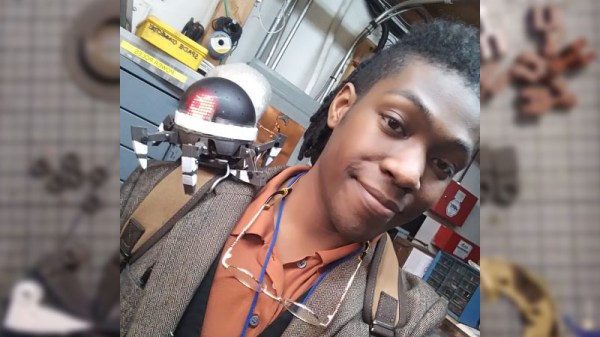
Tricking A Vintage Clock Chip Into Working On 50-Hz Power

Thanks to microcontrollers, RTC modules, and a plethora of cheap and interesting display options, digital clock projects have become pretty easy. Choose to base a clock build around a chip sporting a date code from the late 70s, though, and your build is bound to be more than run-of-the-mill.

This is the boat that [Fran Blanche] finds herself in with one of her ongoing projects. The chip in question is a Mostek MK50250 digital alarm clock chip, and her first hurdle was find a way to run the clock on 50 Hertz with North American 60-Hertz power. The reason for this is a lesson in the compromises engineers sometimes have to make during the design process, and how that sometimes leads to false assumptions. It seems that the Mostek designers assumed that a 24-hour display would only ever be needed in locales where the line frequency is 50 Hz. [Fran], however, wants military time at 60 Hz, so she came up with a circuit to fool the chip. It uses a 4017 decade counter to divide the 60-Hz signal by 10, and uses the 6-Hz output to turn on a transistor that pulls the 60-Hz output low for one pulse. The result is one dropped pulse out of every six, which gives the Mostek the 50-Hz signal it needs. Sure, the pulse chain is asymmetric, but the chip won’t care, and [Fran] gets the clock she wants. Pretty clever.

[Fran] has been teasing this clock build for a while, and we’re keen to see what it looks like. We hope she’ll be using these outsized not-quite-a-light-pipe LED displays or something similar.

Continue reading “Tricking A Vintage Clock Chip Into Working On 50-Hz Power”

PCBs As Linear Motors

PCBs are exceptionally cheap now, and that means everyone gets to experiment with the careful application of copper traces on a fiberglass substrate. For his Hackaday Prize entry, [Carl] is putting coils on a PCB. What can you do with that? Build a motor, obviously. This isn’t any motor, though: it’s a linear motor. If you’ve ever wanted a maglev train on a PCB, this is the project for you.

This project is a slight extension of [Carl]’s other PCB motor project, the aptly named PCB Motor. For this project, [Carl] whipped up a small, circular PCB with a few very small coils embedded inside. With the addition of a bearing, a few 3D printed parts, and a few magnets, [Carl] was able to create a brushless motor that’s also a PCB. Is it powerful enough to use in a quadcopter? Probably not quite yet.

Like [Carl]’s earlier PCB motor, this linear PCB motor follows the same basic idea. The ‘track’, if you will, is simply a rectangular PCB loaded up with twelve coils, each of them using 5 mil space and trace, adding up to 140 turns. This is bigger than the coils used for the (circular) PCB motor, but that only means it can handle a bit more power.

As for the moving part of this motor, [Carl] is using a 3D printed slider with an N52 neodymium magnet embedded inside. All in all, it’s a simple device, but that’s not getting to the complexity of the drive circuit. We’re looking forward to the updates that will make this motor move, turning this into a great entry for The Hackaday Prize.

Ask Hackaday: What Color Are Your PCBs?

A decade ago, buying a custom-printed circuit board meant paying a fortune and possibly even using a board house’s proprietary software to design the PCB. Now, we all have powerful, independent tools to design circuit boards, and there are a hundred factories in China that will take your Gerbers and send you ten copies of your board for pennies per square inch. We are living in a golden age of printed circuit boards, and they come in a rainbow of colors. This raises the question: which color soldermask is most popular, which is most desirable, and why? Seeed Studio, a Chinese PCB house, recently ran a poll on the most popular colors of soldermask. This was compared to their actual sales data. Which PCB color is the most popular? It depends on who you ask, and how you ask it.
Continue reading “Ask Hackaday: What Color Are Your PCBs?”

Bike-Driven Scarf Knitter Is An Accessory To Warmth

Despite all our technological achievements, humans still spend a lot of time waiting around for trains. Add a stiff winter breeze to the injury of commuting, and you’ve got a classic recipe for misery. [George Barratt-Jones] decided to inject some warmth into this scene by inviting people to knit a free scarf for themselves by riding a bike.

All a person has to do is ride the Cyclo-Knitter for five minutes and marvel at their handiwork. By the time the scarf is finished, they’ve cycled past being cold, and they have something to hold in the warmth. Cyclo-Knitter is essentially an Addi Express knitting machine being belt-driven by a stationary bike. Power is transferred from the bike through large, handmade wooden gears using old bike tire inner tubes as belts. [George] built a wooden tower to hold the machine and give the growing scarf a protected space to dangle.

We love the utility of this project as much as the joy it inspires in everyone who tries it. Check out their scarves and their reactions after the break. We haven’t seen people this happy to see something they weren’t expecting since that billboard that kills Zika mosquitoes.

Continue reading “Bike-Driven Scarf Knitter Is An Accessory To Warmth”

Hacking When It Counts: The Magnetron Goes To War

In 1940, England was in a dangerous predicament. The Nazi war machine had been sweeping across Europe for almost two years, claiming countries in a crescent from Norway to France and cutting off the island from the Continent. The Battle of Britain was raging in the skies above the English Channel and southern coast of the country, while the Blitz ravaged London with a nightly rain of bombs and terror. The entire country was mobilized, prepared for Hitler’s inevitable invasion force to sweep across the Channel and claim another victim.

We’ve seen before that no idea that could possibly help turn the tide was considered too risky or too wild to take a chance on. Indeed, many of the ideas that sprang from the fertile and desperate minds of British inventors went on to influence the course of the war in ways they could never have been predicted. But there was one invention that not only influenced the war but has a solid claim on being its key invention, one without which the outcome of the war almost certainly would have been far worse, and one that would become a critical technology of the post-war era that would lead directly to innovations in communications, material science, and beyond. And the risks taken to develop this idea, the cavity magnetron, and field usable systems based on it are breathtaking in their scope and audacity. Here’s how the magnetron went to war.

Continue reading “Hacking When It Counts: The Magnetron Goes To War”

James Bruton's openDog inverse kinematics

[James Bruton] Is Making A Dog: OpenDog Project

There was a time when a two-legged walking robot was the thing to make. But after seeing years of Boston Dynamic’s amazing four-legged one’s, more DIYers are switching to quadrupeds. Now we can add master DIY robot builder [James Bruton] to the list with his openDog project. What’s exciting here is that with [James’] extensive robot-building background, this is more like starting the challenge from the middle rather than the beginning and we should see exciting results sooner rather than later.

James' motor and ball screws
James’ motor and ball screws

Thus far [James] has gone through the planning stage, having iterated through a few versions using Fusion 360, and he’s now purchased the parts. It’s going to be about the same size as Boston Robotic’s SpotMini and uses three motors for each leg. He considered going with planetary gearboxes on the motors but experienced a certain amount of play, or backlash, with them in his BB-9E project so this time he’s going with ball screws as he did with his exoskeleton. (Did we mention his extensive background?)

Each leg is actually made up of an upper and lower leg, which means his processing is going to have to include some inverse kinematics. That’s where the code decides where it wants the foot to go and then has to compute backwards from there how to angle the legs to achieve that. Again drawing from experience when he’s done it the hard way in the past, this time he’s designed the leg geometry to make those calculations easy. Having written up some code to do the calculations, he’s compared the computed angles with the measurements he gets from positioning the legs in Fusion 360 and found that his code is right on. We’re excited by what we’ve seen so far and bet it’ll be standing and walking in no time. Check out his progress in the video below.

Continue reading “[James Bruton] Is Making A Dog: OpenDog Project”

FPGA Persistently Rick Rolls You

When [Im-pro] wants a display, he wants it to spin.  So he built a persistence of vision (POV) display capable of showing a 12-bit color image of 131 x 131 pixels at 16 frames per second. You can see a video about the project below, but don’t worry, you can view it on your normal monitor.

The project starts with a Java-based screen capture on a PC. Data goes to the display wirelessly to an ESP8266. However, the actual display drive is done by an FPGA that drives the motor, reads a hall effect index sensor, and lights the LEDs.

Continue reading “FPGA Persistently Rick Rolls You”