If you thought “carbon nanotubes” were just some near-future unobtainium used in space elevators, don’t worry, you certainly aren’t alone. In reality, while the technology still has a way to go, carbon nanotube production has already exceeded several thousand tons per year and there are products you can buy today that are using this decidedly futuristic wonder material. Now there’s even one you can put in your pocket.
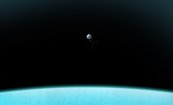
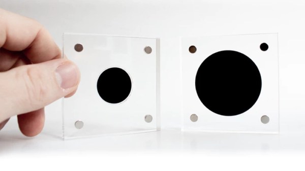
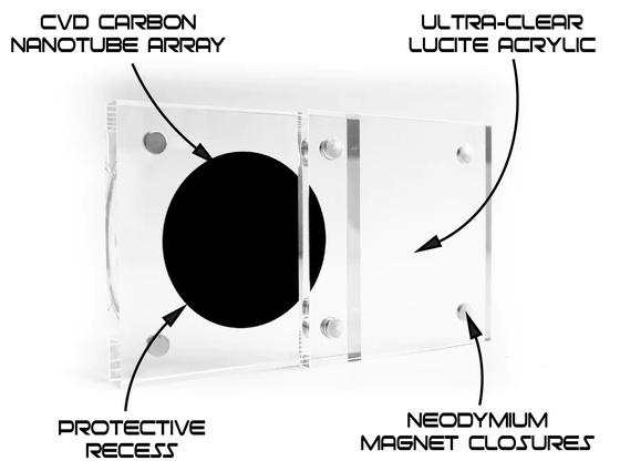 Created by [Simon], a designer in the UK, this small carbon nanotube array is described as “A simulated black hole” because the surface absorbs 99.9% of the visible light that hits it. Protected by a clear acrylic case, the sample of the material makes a circle that’s so black it gives the impression you’re looking into deep space. Unfortunately, no time-dilating gravitational forces are included at any of level of support in the ongoing Kickstarter campaign; but considering it was 100% funded in just a few hours, it seems like most people are OK with the trade-off.
[Simon] is well aware of the ongoing war between different methods of creating the “Blackest Black”, and he thinks he’s put his money (and by extension, his backer’s) money on the winner. Singularity is using a similar technology to the exclusively-licensed Vantablack, rather than a super-dark paint like “Black 3.0”. In fact he’s so confident that Singularity will appear darker than Black 3.0 that he mentions a head-to-head comparison is currently in the works.
If there’s a downside to the carbon nanotube array used in Singularity, it’s that you can’t actually touch it. [Simon] warns that while the acrylic case is only held together with magnets and can be opened for more careful inspection, actually touching the surface is absolutely not recommended. He says that even dust getting on the material is going to adversely effect its ability to absorb light, so you should really keep it buttoned up as much as possible.
While the Singularity looks like an interesting way to experience near perfect blackness, the concept itself is far from a novelty. A material that can absorb essentially all the light that hits it has important scientific, military, and of course artistic applications; so figuring out how to pull it off has become a pretty big deal.