Amateur Astronomer Images Spy Satellite

As anyone who’s looked at the sky just before dawn or right after dusk can confirm, for the last seventy years or so there have been all kinds of artificial satellites floating around in low-Earth orbit that are visible to the naked eye. Perhaps the most famous in the last few decades is the International Space Station, but there are all kinds of others up there from amateur radio satellites, the Starlink constellation, satellite TV, and, of course, various spy satellites from a few of the world’s governments. [Felix] seems to have found one and his images of it can be found here.

[Felix] has been taking pictures of the night sky for a while now, including many different satellites. While plenty of satellites publish their paths to enable use, spy satellites aren’t generally public record but are still able to be located nonetheless. He uses a large Dobsonian telescope to resolve the images of several different satellites speculated to be spy satellites, with at least one hosting a synthetic aperture radar (SAR) system. His images are good enough to deduce the size and shape of the antennas used, as well as the size of the solar panels on board.

As far as being concerned about the ramifications of imaging top-secret technology, [Felix] is not too concerned. He states that it’s likely that most rival governments would be able to observe these satellites with much more powerful telescopes that he has, so nothing he has published so far is likely to be a surprise to anyone. Besides, these aren’t exactly hidden away, either; they’re up in the sky for anyone to see. If you want to take a shot at that yourself you can get a Dobsonian-like telescope mostly from parts at Ikea, and use a bit of off-the-shelf electronics to point them at just the right position too.

Usagi Electric’s Paper Tape Reader Is Ready To Hop With The Tube Computer

After previously working out a suitable approach to create a period-correct paper tape reader for his tube-based, MC14500B processor-inspired computer, [David Lovett] over at the Usagi Electric farm is back with a video on how he made a working tape reader.

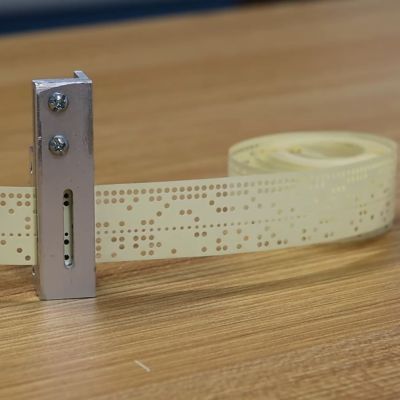
The assembled paper tape reader as seen from the front with tape inserted. (Credit: David Lovett, Usage Electric, YouTube)

The tape reader’s purpose is to feed data into the tube-based computer, which for this computer system with its lack of storage memory means that the instructions are fed into the system directly, with the tape also providing the clock signal with a constant row of holes in the tape.

Starting the tape reader build, [David] opted to mill the structural part out of aluminum, which is where a lot of machining relearning takes place. Ultimately he got the parts machined to the paper design specs, with v-grooves for the photodiodes to fit into and a piece to clamp them down. On top of this is placed a part with holes that line up with the photodiodes.

Another alignment piece is added to hold the tape down on the reader while letting light through onto the tape via a slot. After a test assembly [David] was dismayed that due to tolerance issues he cracked two photodiodes within the v-groove clamp, which was a hard lesson with these expensive (and rare) photodiodes.

Although tolerances were somewhat off, [David] is confident that this aluminum machined reader will work once he has it mounted up. Feeding the tape is a problem that is still to be solved.  [David] is looking for ideas and suggestions for a good approach within the limitations that he’s working with. At the video’s end, he mentions learning FreeCAD and 3D printing parts in the future.  That would probably not be period-correct in this situation, but might be something he could get away with for some applications within the retrocomputing space.

We covered the first video and the thought process behind picking small (1.8 mm diameter) photodiodes as a period-correct tape hole sensor for a 1950s-era computing system, like the 1950s Bendix G-15 that [David] is currently restoring.

Continue reading “Usagi Electric’s Paper Tape Reader Is Ready To Hop With The Tube Computer”

IBM’s 1969 Educational Computing

IBM got their PCs and PS/2 computers into schools in the 1980s and 1990s. We fondly remember educational games like Super Solvers: Treasure Mountain. However, IBM had been trying to get into the educational market long before the PC. In 1969, the IBM Schools Computer System Unit was developed. Though it never reached commercial release, ten were made, and they were deployed to pilot schools. One remained in use for almost a decade! And now, there’s a new one — well, a replica of IBM’s experimental school computer by [Menadue], at least. You can check it out in the video below.

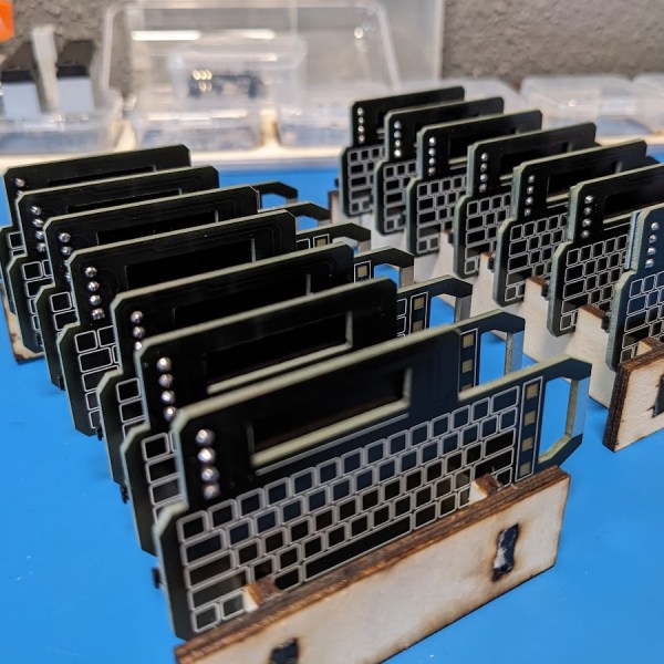
The internals were based somewhat on the IBM System/360’s technology. Interestingly, it used a touch-sensitive keypad instead of a traditional keyboard. From what we’ve read, it seems this system had a lot of firsts: the first system to use a domestic TV as an output device, the first system to use a cassette deck as a storage medium, and the first purpose-built educational computer. It was developed at IBM Hursley in the UK and used magnetic core memory. It used BCD for numerical display instead of hexadecimal or octal, with floating point numbers as a basic type. It also used 32-bit registers, though they stored BCD digits and not binary. In short, this thing was way ahead of its time.

Continue reading “IBM’s 1969 Educational Computing”

DOOM On A Volumetric Display

There’s something magical about volumetric displays. They really need to be perceived in person, and no amount of static or video photography will ever do them justice. [AncientJames] has built a few, and we’re reporting on his progress, mostly because he got it to run a playable port of DOOM.

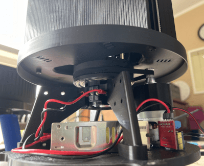
Base view of an earlier version showing the motor drive and PSU

As we’ve seen before, DOOM is very much a 3D game viewed on a 2D display using all manner of clever tricks and optimizations. The background visual gives a 3D effect, but the game’s sprites are definitely very solidly in 2D land. As we’ll see, that wasn’t good enough for [James].

The basic concept relies on a pair of 128 x 64 LED display matrix modules sitting atop a rotating platform. The 3D printed platform holds the displays vertically, with the LEDs lined up with the diameter, meaning the electronics hang off the back, creating some imbalance.

Lead, in the form of the type used for traditional window leading, was used as a counterbalance. A Raspberry Pi 4 with a modified version of this LED driver HAT is rotating with the displays. The Pi and both displays are fed power from individual Mini560 buck modules, taking their input from a 12 V 100 W Mean-Well power supply via a car alternator slip ring setup. (Part numbers ABH6004S and ASL9009  for those interested.) Finally, to synchronise the setup, a simple IR photo interrupter signals the Pi via an interrupt.

Continue reading DOOM On A Volumetric Display”

A Windows Control Panel Retrospective Amidst A Concerning UX Shift

Once the nerve center of Windows operating systems, the Control Panel and its multitude of applets has its roots in the earliest versions of Windows. From here users could use these configuration applets to control and adjust just about anything in a friendly graphical environment. Despite the lack of any significant criticism from users and with many generations having grown up with its familiar dialogs, it has over the past years been gradually phased out by the monolithic Universal Windows Platform (UWP) based Settings app.

Whereas the Windows control panel features an overview of the various applets – each of which uses Win32 GUI elements like tabs to organize settings – the Settings app is more Web-like, with lots of touch-friendly whitespace, a single navigable menu, kilometers of settings to scroll through and absolutely no way to keep more than one view open at the same time.

Unsurprisingly, this change has not been met with a lot of enthusiasm by the average Windows user, and with Microsoft now officially recommending users migrate over to the Settings app, it seems that before long we may have to say farewell to what used to be an intrinsic part of the Windows operating system since its first iterations. Yet bizarrely, much of the Control Panel functionality doesn’t exist yet in the Settings app, and it remain an open question how much of it can be translated into the Settings app user experience (UX) paradigm at all.

Considering how unusual this kind of control panel used to be beyond quaint touch-centric platforms like Android and iOS, what is Microsoft’s goal here? Have discovered a UX secret that has eluded every other OS developer?

Continue reading “A Windows Control Panel Retrospective Amidst A Concerning UX Shift”

Make Your Own Point Contact Transistor

Beyond the power variant, it sometimes seems as though we rarely encounter a discrete transistor these days, such has been the advance of integrated electronics. But they have a rich history, going back through the silicon era to germanium junction transistors, and thence to the original devices. if you’ve ever looked at the symbol for a transistor and wondered what it represents, it’s a picture of those earliest transistors, which were point contact devices. A piece of germanium as the base had two metal electrodes touching it as the emitter or collector, and as [Marcin Marciniak] shows us, you can make one yourself (Polish language, Google Translate link).

These home made transistors sacrifice a point contact diode to get the small chip of germanium, and form the other two electrodes with metal foil glued to paper. Given that germanium point contact diodes are themselves a rarity these days we’re guessing that some of you will be wincing at that. The video below is in Polish so you’ll have to enable YouTube’s translation if you’re an Anglophone — but we understand that the contact has to be made by passing a current through it, and is then secured with a drop of beeswax.

A slight surprise comes in how point contact transistors are used, unlike today’s devices their gain in common emitter mode was so poor that they took instead a common base configuration. There’s a picture of a project using three of them, a very period radio receiver with bulky transformers between all stages.

If you’re interested in more tales of home made early transistors, read our feature on Rufus Turner.

Continue reading “Make Your Own Point Contact Transistor”

Is That Antenna Allowed? The Real Deal On The FCCs OTARD Rule

The Hackaday comments section is generally a lively place. At its best, it’s an endless wellspring of the combined engineering wisdom of millions of readers which serves to advance the state of the art in hardware hacking for all. At its worst — well, let’s just say that at least it’s not the YouTube comments section.

Unfortunately, there’s also a space between the best and the worst where things can be a bit confusing. A case in point is [Bryan Cockfield]’s recent article on a stealth antenna designed to skirt restrictions placed upon an amateur radio operator by the homeowners’ association (HOA) governing his neighborhood.

Hiding an antenna in plain sight.

Putting aside the general griping about the legal and moral hazards of living under an HOA, as well as the weirdly irrelevant side-quest into the relative combustibility of EVs and ICE cars, there appeared to be a persistent misapprehension about the reality of the US Federal Communications Commission’s “Over-the-Air Reception Devices” rules. Reader [Gamma Raymond] beseeched us to clarify the rules, lest misinformation lead any of our readers into the unforgiving clutches of the “golf cart people” who seem to run many HOAs.

According to the FCC’s own OTARD explainer, the rules of 47 CFR § 1.400 are intended only to prevent “governmental and nongovernmental restrictions on viewers’ ability to receive video programming signals” (emphasis added) from three distinct classes of service: direct satellite broadcasters, broadband radio service providers, and television broadcast services.

Specifically, OTARD prevents restrictions on the installation, maintenance, or use of antennas for these services within limits, such as dish antennas having to be less than a meter in diameter (except in Alaska, where dishes can be any size, because it’s Alaska) and restrictions on where antennas can be placed, for example common areas (such as condominium roofs) versus patios and balconies which are designated as for the exclusive use of a tenant or owner. But importantly, that’s it. There are no carve-outs, either explicit or implied, for any other kind of antennas — amateur radio, scanners, CB, WiFi, Meshtastic, whatever. If it’s not about getting TV into your house in some way, shape, or form, it’s not covered by OTARD.

It goes without saying that we are not lawyers, and this is not to be construed as legal advice. If you want to put a 40′ tower with a giant beam antenna on your condo balcony and take on your HOA by stretching the rules and claiming that slow-scan TV is a “video service,” you’re on your own. But a plain reading of OTARD makes it clear to us what is and is not allowed, and we’re sorry to say there’s no quarter for radio hobbyists in the rules. This just means you’re going to need to be clever about your antennas. Or, you know — move.