Dr. Robert Hecht-Nielsen, inventor of one of the first neurocomputers, defines a neural network as:
“…a computing system made up of a number of simple, highly interconnected processing elements, which process information by their dynamic state response to external inputs.”
These ‘processing elements’ are generally arranged in layers – where you have an input layer, an output layer and a bunch of layers in between. Google has been doing a lot of research with neural networks for image processing. They start with a network 10 to 30 layers thick. One at a time, millions of training images are fed into the network. After a little tweaking, the output layer spits out what they want – an identification of what’s in a picture.
The layers have a hierarchical structure. The input layer will recognize simple line segments. The next layer might recognize basic shapes. The one after that might recognize simple objects, such as a wheel. The final layer will recognize whole structures, like a car for instance. As you climb the hierarchy, you transition from fast changing low level patterns to slow changing high level patterns. If this sounds familiar, we’ve talked out about it before.
Now, none of this is new and exciting. We all know what neural networks are and do. What is going to blow your  mind, however, is a simple question Google asked, and the resulting answer. To better understand the process, they wanted to know what was going on in the inner layers. They feed the network a picture of a truck, and out comes the word “truck”. But they didn’t know exactly how the network came to its conclusion. To answer this question, they showed the network an image, and then extracted what the network was seeing at different layers in the hierarchy. Sort of like putting a serial.print in your code to see what it’s doing.
They then took the results and had the network enhance what it thought it detected. Lower levels would enhance low level features, such as lines and basic shapes. The higher levels would enhance actual structures, such as faces and trees.  This technique gives them the level of abstraction for different layers in the hierarchy and reveals its primitive understanding of the image. They call this process inceptionism.
Be sure to check out the gallery of images produced by the process. Some have called the images dream like, hallucinogenic and even disturbing. Does this process reveal the inner workings of our mind? After all, our brains are indeed neural networks. Has Google unlocked the mind’s creative process? Or is this just a neat way to make computer generated abstract art.
So here comes the big question: Is it the computer chosing these end-product photos or a google engineer pawing through thousands (or orders of magnitude more) to find the ones we will all drool over?



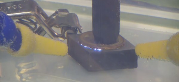
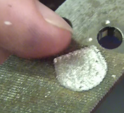 As you can imagine, a single spark won’t erode much metal. EDM machines fire tens of thousands of times per second. The exact frequencies, voltages, and currents are secrets the machine manufacturers keep close to their chests. [SuperUnknown] is zeroing in on 65 volts at 2 amps, running at 35 kHz. He’s made some great progress, gouging into hardened files, removing broken taps from brass, and even eroding the impression of a coin in steel.
 mind, however, is a simple question Google asked, and the resulting answer. To better understand the process, they wanted to know what was going on in the inner layers. They feed the network a picture of a truck, and out comes the word “truck”. But they didn’t know exactly how the network came to its conclusion. To answer this question, they showed the network an image, and then extracted what the network was seeing at different layers in the hierarchy. Sort of like putting a serial.print in your code to see what it’s doing.
 This technique gives them the level of abstraction for different layers in the hierarchy and reveals its primitive understanding of the image. They call this process