Valentine Heart

Animated LED Valentine Heart

With only a week left until Valentine’s day, [Henry] needed to think on his feet. He wanted to build something for his girlfriend but with limited time, he needed to work with what he had available. After scrounging up some parts and a bit of CAD work, he ended up with a nice animated LED Valentine heart.

[Henry] had a bunch of WS2812 LEDs left over from an older project. These surface mount LED’s are very cool. They come in a small form factor and include red, green, and blue LEDs all in a single package. On top of that, they have a built-in control circuit which makes each LED individually addressable. It’s similar to the LED strips we’ve seen in the past, only now the control circuit is built right into the LED.

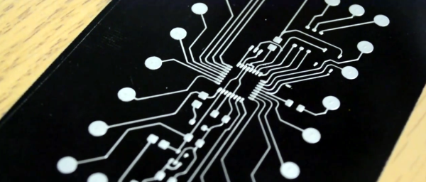
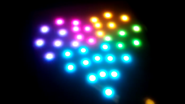
Starting with the LEDs, [Henry] decided to build a large animated heart. Being a stickler for details, he worked out the perfect LED placement by beginning his design with three concentric heart shapes. The hearts were plotted in Excel and were then scaled until he ended up with something he liked. This final design showed where to place each LED.

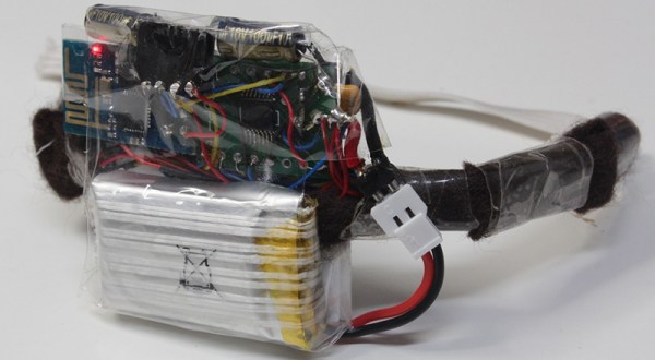
The next step was to design the PCB in Altium Designer. [Henry’s] design is two-sided with large copper planes on either side. He opted to make good use of the extra copper surface by etching a custom design into the back with his girlfriend’s name. He included a space for the ATMega48 chip which would be running the animations. Finally, he sent the design off to a fab house and managed to get it back 48 hours later.

After soldering all of the components in place, [Henry] programmed up a few animations for the LEDs. He also built a custom frame to house the PCB. The frame includes a white screen that diffuses and softens the light from the LEDs. The final product looks great and is sure to win any geek’s heart. Continue reading “Animated LED Valentine Heart”

Ask Hackaday: Are Conductive Inks Going To Make It?

It’s amazing how affordable PCB fabrication has become. It has long been economical (although not always simple) to fabricate your own singe and double-sided boards at home, the access to professional fabrication is becoming universal. The drive continues downward for both cost and turnaround time. But there is growing interest in the non-traditional.

Over the last year we’ve seen a huge push for conductive-ink-based PCB techniques. These target small-run prototyping and utilize metals (usually silver) suspended in fluid (think glue) to draw traces rather than etching the traces out of a single thin layer of copper. Our question: do you think conductive in will become a viable prototyping option?

Voltera V-One Circuit Board Prototyping Machine

I recorded this interview at 2015 CES but was asked not to publish it until their crowd funding campaign went live. If you haven’t been paying attention, Voltera is at almost 400% of their $70k goal with 26 days remaining. This printer definitely works. You can print circuits, solder components or reflow them, and there’s even a second non-conductive ink that can be used to insulate between traces when they cross over one another. In the video [Alroy] suggests Voltera for small production runs of 10-20 boards. Would you see yourself using this for 10-20 boards?

Personally, I think I could solder point-to-point prototypes in less time. Consider this: the V-One will print your traces but you still must solder on the components yourself. If the board design reaches a high level of complexity, that timing may change, but how does the increased resistance of the ink compared to copper traces affect the viability of a board? I assume that something too complex to solder point-to-point would be delving into high-frequency communications (think parallel bus for LCD displays, etc.). Is my assumption correct? Do you think conductive ink will get to the point that this is both viable and desirable over etching your own prototypes and how long before we get there?

Now, I certainly do see some perfect use-cases for Voltera. For instance, introduction to circuit design classes. If you had one of these printers at the middle school or high school level it would jump-start interest in electronics engineering. Without the need for keeping chemical baths like Cuperic Chloride or Ferric Chloride on hand, you could walk students through simple board design and population, with the final product to take home with them. That’s a vision I can definitely get behind and one that I think will unlock the next generation of hardware hackers.

Correction: [Arachnidster] pointed out in the comments that Voltera is still working on being able to reflow boards printed by the V-One. On their Kickstarter page they mention: “(Reflow onto Voltera printed boards is currently under development)”

Hacklet 34 – Satellite Projects

Space. The final frontier. Every tinkerer, hacker, and maker has dreamed of flying out of Earth’s atmosphere and into the heavens. Last year one hard-working team got a chance to fly a member to space by winning the Hackaday prize. For the rest of us, we can still experience some of that excitement by contacting satellites in orbit, or even sending a bit of our own hardware into space. This week’s Hacklet focuses on the best satellite projects on Hackaday.io!

basicSatWe start with [movax] and Your satellite devkit and launch. Chipsat is a tiny satellite which runs BASIC code. Yes, BASIC in space! Chipsats will be stacked into a launcher and sent off into space in groups. The idea is to eventually have them launched from the International Space Station. Power is provided by a small solar cell which charges up a pair of super capacitors. When the capacitors are charged, the satellite will run for a few seconds. Connectivity with the ground is via a 433 MHz link. Chipsat doesn’t just float in space, three coils give it the ability to control its attitude and rotation. Chipsat will sense the space around it with a magnetometer and a light sensor.


satnogsv2

No satellite-themed Hacklet would be complete without [Pierros Papadeas] and his team’s work on SatNOGS – Global Network of Ground Stations. SatNOGS aims to create a global network of connected satellite ground stations. Think of it as a grass-roots version of NASA’s deep space network for satellites in earth orbit. This is more than just a great idea, as SatNOGS won the 2014 Hackaday Prize. You can check out our coverage of the project back in November, 2014. Since then, the SatNOGS team has been busy! They’ve just deployed the first SatNOGS V2 system above their hackerspace in Athens, Greece.

trsiNext up is TRSI PocketQub Satellite, another project by [movax]. TRSI is a satellite that sends data via images which can be viewed with a simple RTL-SDR stick using Hellschreiber mode. Hell mode means that images can be directly viewed in the waterfall display of whichever SDR application is running the receiver. Numbers or entire images snapped with TRSI’s cell phone style camera module can be encoded and displayed. Power is of course provided by solar cells, and the communications link will be on the coordinated 433 MHz band. The original TRSI hardware has actually morphed into a deployment machine for ChipSat, [morvax’s] other satellite project. He’s put the main TRSI program on hold until after the ChipSat campaign is complete.

pocketquRounding out our satellite special is [OzQube] with his project QubeCast Max. QubeCast is the first Australian version of the PocketQube PQ60 satellite form factor. After watching the success of $50Sat project, [OzQube] wanted to design a satellite of his own. Since he wanted to add sensors and send more data back to Earth than previous efforts, he needed a higher data rate than the current crop of satellites. This meant going to a high-powered radio. To achieve this, he’s using a  NiceRF RF4463F30 radio module. The module is based upon a Silicon Labs Si4463 RF ISM band chip, coupled with a power amplifier. The module outputs 1 watt, which is quite a bit of power for a tiny satellite!

Want more satellite goodness? Check out Hackaday.io’s freshly minted Satellite List.

The countdown is almost at 0, so that’s just about all the time we have for this episode of the Hacklet. See you next week.  Same hack time, same hack channel, bringing you the best of Hackaday.io!

HDMI Audio And Video For Neo Geo MVS

[Charlie] was killing some time hacking on some cheap FPGA dev boards he bought from eBay. Initially, he intended to use them to create HDMI ports for a different project before new inspiration hit him. Instead, he added an HDMI port to Neo Geo MVS games. The Neo Geo MVS was a 90’s arcade machine that played gems like the Metal Slug and Samurai Showdown series. [Charlie] has a special knack for mods, being featured on Hackaday before for implementing Zork on hardware and making a mini supergun PCB. What’s especially nice about his newest mod is that the HDMI outputs both audio and video.

[Charlie] obtained the best possible video and audio signal by tapping the digital inputs to the Neo Geo’s DACs (digital-to-analog converter). The FPGA was then used to convert the signals to HDMI, maintaining a digital signal path from video generation to display. While this sounds simple enough, there was a lot that had to be done. The JAMMA video standard’s lower resolution was incompatible with the various resolutions offered by the HDMI protocol. [Charlie] solved this problem by implementing scan doubling using the RAM on the Cyclone II dev board. He then had to downsample the audio to 32kHz (from 55.6kHz) in order to meet the HDMI specs. Getting the sound over HDMI required adding data islands to the signal, a feat [Charlie] admits was a frustrating one.

When he tested the HDMI with his monitor, it was out of spec but still worked. His TV, on the other hand, refused to play it at all. This was due to the Neo Geo outputting 59.1 fps – not the standard 60 fps. Using the FPGA, [Charlie] overclocked the NeoGeo by approximately 1% and used the 27Mhz pixel clock to change the FPGA output to a 720 x 480p signal.

For those that love the scan lines of yore, they can be enabled with the push of a button. [Charlie] notes that there are some slight differences in the shadow effects of some graphics, but he has done his best to minimize them. He also admits that the FPGA code contributes only 100 microseconds of delay compared to analog output, which is fast enough for even the most hardcore gamers.

Check out the video after the break to see how the Neo Geo looks in HDMI along with a side-by-side comparison to a CRT TV.

Continue reading “HDMI Audio And Video For Neo Geo MVS”

Teletext On A Raspi With Zero Additional Parts

Way back in the 70s, the UK and BBC rolled out teletext – an information retrieval service that’s much closer to the ‘television screens connected to computers the size of a room’ popularized by 1960s futurists than the Internet and world wide web. For about 30 years, teletext was one of the most reliable means of information distribution until it was quietly shelved with the rollout of digital television.

Playing with dead protocols is fun, though, and since the Raspberry Pi has an analog video out, [Alistair] thought it would be fun to turn his Pi into a teletext generator and display.

This isn’t [Alistair]’s first teletext rodeo; earlier he built an add-on board for the Raspi that uses an AVR and an LM1881 video sync separator to mux the video output of a Raspi with teletext signals. The new build does away with this completely, allowing any Raspberry Pi to generate and display information from a teletext service. Right now there are two demos, a Raspi status display that shows the CPU frequency, usage, memory, and temperature. There’s also a ‘clock cracker’ with a picture of Tux that should help diagnose reception issues.

All the code is available on the project’s github, although [Alistair] hasn’t released the scripts to output teletext pages captured from broadcast signals years ago.

Continue reading “Teletext On A Raspi With Zero Additional Parts”

Ridiculously Complicated Home Automation Made Simple

[Eric T] wrote up his insanely-comprehensive home automation setup. What started out as a method to notify him when his dog barked grew into a whole-house, Arduino-powered sensor extravaganza. We’ve previously looked at two different steps from this mammoth article. One automated his dog, the other focused on the Wink hub to bridge with commercial hardware like smart lightbulbs. Now let’s look at the project as a whole.

The basic backbone of the project is actually quite straightforward. He made a radio gateway base station out of an Arduino, a RFM69 radio unit, and an Ethernet shield that connects to a Raspberry Pi to serve up a GUI interface. The open-source home automation project OpenHAB makes it all available through browser or smartphone.

Next, he made additional sensor nodes from Arduino and RMF69 radios. These sensor nodes can all be separate from each other, which has enabled [Eric] to expand his system incrementally over time.

Modules of particular interest are the Uber Sensor and the Washer-Dryer module. For the Uber Sensor, [Eric] basically threw every sensor he could at an Arduino; it sends noise levels, light levels, motion, temperature, humidity, and presence of smoke, flame, or flammable gas. Some of these conditions trigger e-mail alerts, while others are simply stored for future perusal.

On the simpler end of the spectrum, he uses a noise-level detector to detect the end of a laundry cycle and then trigger a notification. The clever bit is that the message is automatically cleared when an attached motion detector triggers, presumably because someone’s gone to the basement to empty the dryer. Very neat.

16All of this is basically made practical and affordable by the presence of simple Arduino libraries and cheap hardware modules purchasable over Ebay. If you’re at all interested in a DIY home automation project, this offering is worth a look for inspiration and a great overview.

A Haptic Bracelet For Physical Computing

[Tinkermax] has been reading about the Internet of Things and wearable computing and decided it was time for him to have a go at building a device that turned computing physical. The result is a vibrating wristband that connects his sense of touch to the Internet.

The electronics for this haptic wristband are a mix of old and new technology. The radio and microcontroller come from an ESP-8266 module that was programmed with [Mikhail Grigorev]’s unofficial SDK. The mechanics for the wrist-mounted computer consist of six pager motors mounted around the wrist. These are driven somewhat ingeniously by a TLC5917 LED driver chip. This meant the ESP would only need to use two of its GPIOs to control six motors.

Right now the software is simple enough; just a web page, a few buttons, and the ability to buzz any of the pager motors on the wrist band over the Internet. Now it’s just a question of making this wearable useful, but connecting each pager motor to different notifications – a new email, a new SMS, or some emergency on the Internet – should be pretty easy.

Video below.

Continue reading “A Haptic Bracelet For Physical Computing”