This excellent content from the Hackaday writing crew highlights recurring topics and popular series like Linux-Fu, 3D-Printering, Hackaday Links, This Week in Security, Inputs of Interest, Profiles in Science, Retrotechtacular, Ask Hackaday, Teardowns, Reviews, and many more.
In a recent posting called Liar’s 3D Printing, I showed you how you can print with multiple filament colors even if your printer only has one extruder and hot end. It isn’t easy, though, and a lot of models you’ll find on sites like Thingiverse are way too complicated to give good results. An object with 800 layers, each with two colors is going to take a lot of filament changes and only the most patient among us will tolerate that.
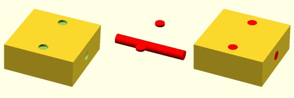
What that means is you are likely to want to make your own models. The question is, how? The answer is, of course, lots of different ways. I’m going to cover how I did the two models I showed last time using OpenSCAD (seen below). The software is actually really well suited for this hack, making it easy for me to create a framework of several models to represent the different colors.
About OpenSCAD
I’m not going to say much about OpenSCAD. It is less a CAD package and more a programming language that lets you create shapes. We’ve covered it before although it changes from time to time so you might be better off reading the official manual.
The general idea, though, is you use modules to create primitives. You can rotate them and translate them (that is, move them). You can also join them (union) and take the difference of them (difference). That last is especially important. For example, look at the callsign plate above. Forget the text for now. See the two holes? Here’s the OpenSCAD that creates that shape:
The cube “call” creates the base. The cylinders are the holes and the difference “call” is what makes them holes instead of solid cylinders (the first thing is the solid and everything after is taken away). One key point: instead of numbers, the whole thing uses (mostly) variables. That means if you change the size of something, everything will adjust accordingly if you wrote the script well. Let’s look at applying these techniques for multiple colors.
Today on Hackaday Dictionary, we’re going to talk about the two basic types of control systems: open-loop and closed-loop. We’ll describe the differences between them and explore the various advantages and disadvantages of each. And finally, we’ll talk about what happens when you try to draw a line between the two.
Control systems are literally all around us. They’re illuminating our rooms, laundering our unmentionables, and conspiring to make us late for work. Most of us probably use or interact with at least five control systems before we’re even out the door in the morning. Odds are you’re using a control system to read this article.
When we say ‘control system’, we’re speaking broadly. A control system is defined as any system that exhibits control over a function. It doesn’t matter how big or small the function is. A standard light switch is a simple type of control system. Flip it back and forth and the light is either on or off with no in between. Too bright? Too bad. There is no way to account for light intensity preference, use duration, energy output, or anything else.
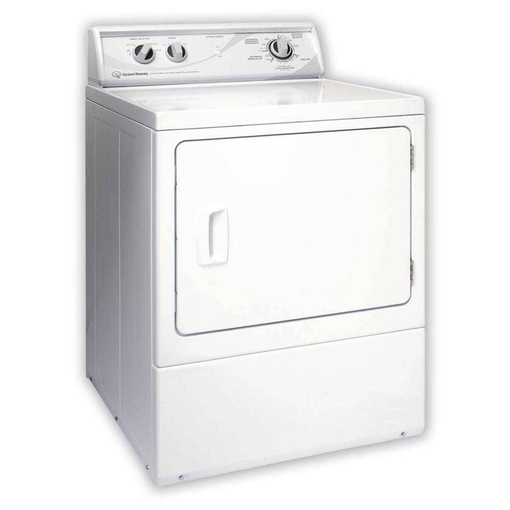
Another common example in discussing control system theory is the clothing dryer. Set the timer on the dryer and it will run until time expires. Will it run long enough to dry everything without shrinking anything? The only way to know is to open the door and check.
Both the light switch and the clothes dryer are open-loop systems. The process is a straight line from start to finish, and they operate without concern for their output. Once the light switch is flipped to the on position, current will flow until the switch is reversed. The switch doesn’t know if the bulb is burned out or even screwed into the socket to begin with. And the clothes dryer doesn’t care if your clothes are damp or dry or totally shrunken when time runs out.
Stay in the Loop
In a closed-loop system, the process begins the same way it does in an open-loop system. But a closed-loop system has one or more feedback loops in place that can adjust the process. Sometimes the feedback will simply cause the process to repeat until the desired result is achieved.
Both of our open-loop control system examples above could easily be converted to closed-loop systems. A more advanced light switch might take input from a photo cell, or it could poll a motion detector and turn the lights off after a period of no detectable activity in the room. The clothes dryer could be improved with the addition of a moisture sensor. Since the humidity level in the dryer will change during the cycle, why not poll a DHT22 and re-run the process until a predetermined humidity level is reached? Then the dryer becomes a closed-loop system. No more reaching in and fondling the towels and shirt collars to make sure everything is dry. Well, at least in theory.
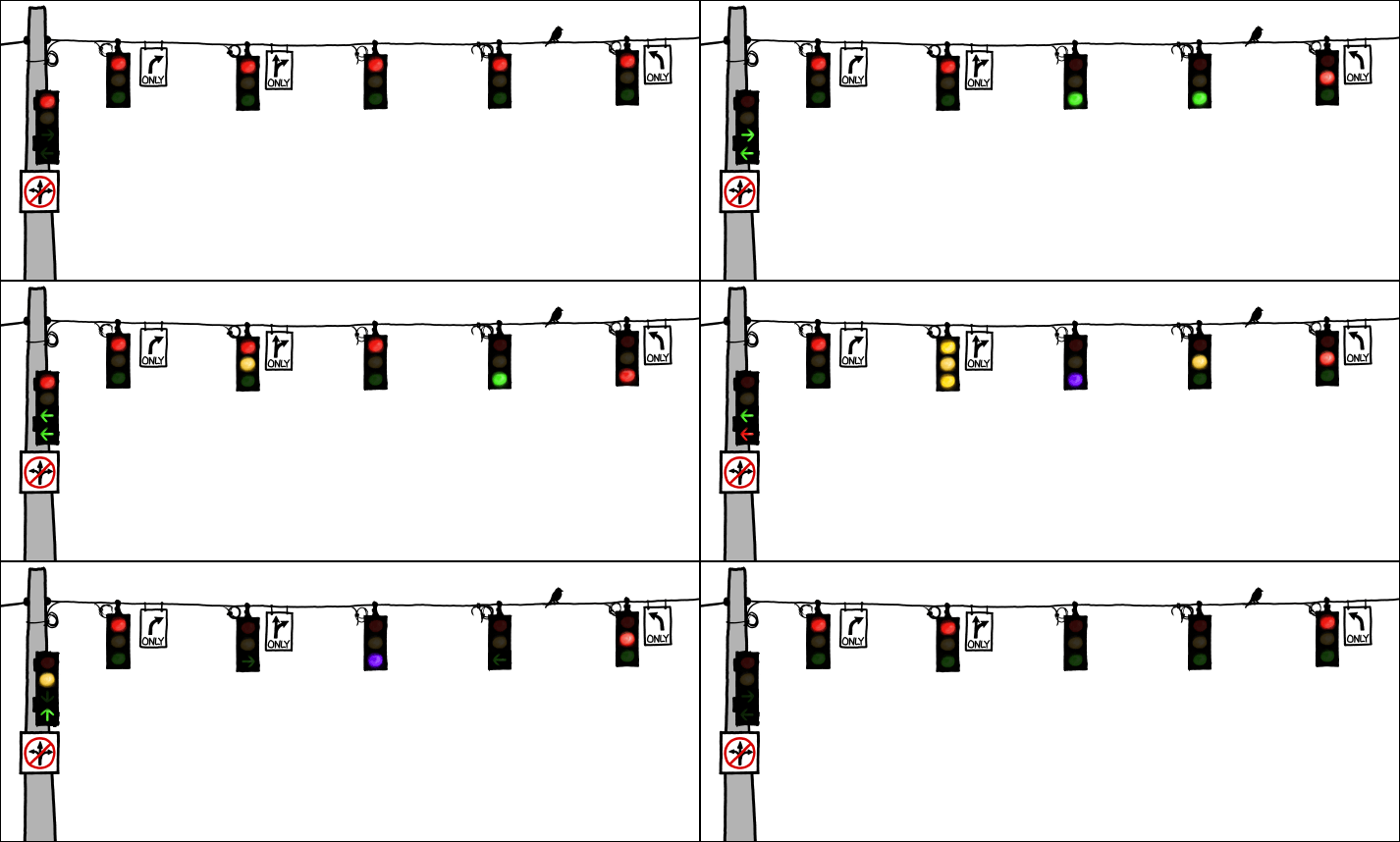
Some control systems exist in both forms. Traffic lights are a good example of this phenomenon. Some lights are open-loop and simply run on a schedule. Many more of them are closed-loop and will cycle differently depending on traffic flow or information received from other traffic lights. The really smart ones have Emergency Vehicle Preemption (EVP) receivers. This is the system that allows fire trucks and some other emergency vehicles to change the lights in their favor. A device in the vehicle strobes a specific pattern at the receiver module on the light post, and the light changes as soon as possible.
The main advantage of closed-loop systems is fairly obvious: using feedback means more and better control. But there are trade-offs. It’s almost impossible to deal with all the what-ifs in creating any system, and this generates unforeseen issues. They aren’t all bad, though. Maybe you’re sitting peacefully in the corner engrossed in a book, and the motion detector-driven lights shut off because you aren’t moving around enough. That isn’t ideal, but it’s easy enough to turn the lights back on and keep reading.
The unforeseen issues can be so much worse than sudden darkness. Case in point: robotic vacuum cleaners. Here you have a complexly closed-loop system to take care of one of life’s drudgeries. Should be awesome, right? Yes, but because it is blind to everything but its pre-programmed boundaries, it doesn’t know not to spread messes around.
A lot of closed-loop control systems look great on paper, but their imperfections become clear in execution. Take cruise control for example. Here is a system that’s better at its job than humans are. It will maintain the set speed until you hit the brakes or run out of gas. It will perform as intended whether there is a headwind or a tailwind or you’re towing a boat or transporting rowdy children. But cruise control isn’t aware of cliffs or guard rails or deer darting out in front of the car. Cruise control keeps its head down and does its job until it can’t go on.
Open-loop systems may not be as smart as closed-loop systems, but they often shine in their simplicity. For the most part, they do what you expect them to do. Light goes on, light goes off. And they are arguably more dependable since there are fewer things that can go wrong. Of course, a “simple” open-loop control system can mean a steeper learning curve. It’s not easy to learn to drive a manual transmission. But if you don’t know how to drive one, you’re missing out on some nice advantages, like the ability to push start the thing if you have to, and the option to downshift instead of pumping the brakes in icy conditions. So the question is this: is an open-loop system more valuable than a closed-loop system if it means having more control over the process? Does it depend entirely on the process in question?
This tricycle is simultaneously safe and unsafe. Image via Apple Door
Open-Loop vs. Closed-Loop
So where exactly does open-loop end and closed-loop begin? The line seems clear for some systems, but muddy for others. How much feedback is enough to qualify? Add just about anything to a light switch and it seems safe to say that you took it from open- to closed-loop.
More often than not, the line between the two is blurry. Think of a motorized garage door. You push the button and the door either opens or closes. Push it again and the door moves in the opposite direction. Most modern garage doors have a fail-safe in place to stop the garage door in the event of an emergency. If the door encounters any resistance, it will stop and reverse direction.
The break beam detector is supposed to keep people and their tricycles from being crushed if they happen to be in the way while the door is closing. But it only works if the person or thing breaks the IR beam. There’s only one beam, and it sits about six inches off the floor. The motorized garage door system is actually quite limited because it has no positional awareness. It doesn’t know where it is on the track, it’s just going up and down blindly, waiting for input or resistance.
Not all doors can be counted on to stop if they feel resistance—I tested mine and it kept on going. So if I don’t pull far enough into the garage and then put the door back down, it might hit the protruding rear end of my hatchback. It’s in the way of the door closing, but it sits way too high to break the beam. So is the garage door really, truly a closed-loop system?
Recently, [Manuel] did a post on making logic gates out of anything. He mentioned a site about relay logic. While it is true that you can build logic gates using switch logic (that is, two switches in series are an AND gate and two in parallel are an OR gate), it isn’t the only way. If you are wiring a large circuit, there’s some benefit to having regular modules. A lot of computers based on discrete switching elements worked this way: you had a PCB that contained some number of a basic gate (say, a two input NAND gate) and then the logic was all in how you wired them together. And in this context, the SPDT relay was used as a two input multiplexer (or mux).
In case you think the relay should be relegated to the historical curiosity bin, you should know there are still applications where they are the best tool for the job. If you’re not convinced by normal macroscopic relays, there is some work going on to make microscopic relays in ICs. And even if they don’t use relays to do it, some FPGAs use mux-based logic inside. So it’s worth your time to dig into the past and see how simply switching between two connections can make a computer.
Mux Mania
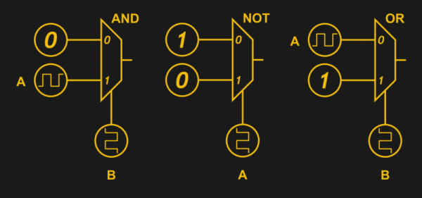
How do you go from a two input mux to an arbitrary logic gate? Simple, if you paid attention to the banner image. (Or try it interactive). The mux symbols show the inputs to the left, the output to the right and the select input at the bottom. If the select is zero, the “0” input becomes the output. If the select is one, the “1” input routes to the output.
KiCad is the premiere open source electronics design automation suite. It’s used by professionals and amateurs alike to design circuits and layout out printed circuit boards. In recent years we’ve seen some incredible features added to KiCad like an improved 3D viewer and push-and-shove routing. This Friday at 10 am PST, join in a Hack Chat with KiCad lead developer [Wayne Stambaugh] to talk about recent improvements and what the team has planned for KiCad in the future.
[Wayne] has been an electronics engineer for over 30 years with a wide range of experience in analog and digital hardware design and embedded and application software design. He started hacking on KiCad ten years ago when the project was first opened to public development and a little over two years ago became the project leader. This is an excellent opportunity to learn how the development team works, what their current goals are, and to talk all things KiCad.
Also on Friday, taking place just an hour before the KiCad chat, is a Tindie Hack Chat. All are welcome as the 9:00 am PST discussion gets under way. Discussion will focus on all aspects of selling unique hardware on Tindie.
Here’s How to Take Part:
Buttons to join the project and enter Hack Chat
Hack Chat are live community events that take place in the Hackaday.io Hack Chat group messaging. Visit that page (make sure you are logged in) and look for the “Join this Project Button” in the upper right. Once you are part of the project, that button will change to “Team Messaging” which takes you to the Hack Chat.
You don’t have to wait for Friday, join Hack Chat whenever you like and see what the community is currently talking about.
Join Us Next Week Too for CircuitPython
Block out your calendar for noon PST on Friday the 27th for next week’s Hack Chat. Joining us are Adafruit’s Ladyada, Tony DiCola, and Scott Shawcoft. They’ll be leading a discussion about CircuitPython Beta, Adafruits new extension to MicroPython that adds SAMD21 support and other enhancements.
Accurate timing is one of the most basic requirements for so much of the technology we take for granted, yet how many of us pause to consider the component that enables us to have it? The quartz crystal is our go-to standard when we need an affordable, known, and stable clock frequency for our microprocessors and other digital circuits. Perhaps it’s time we took a closer look at it.
The first electronic oscillators at radio frequencies relied on the electrical properties of tuned circuits featuring inductors and capacitors to keep them on-frequency. Tuned circuits are cheap and easy to produce, however their frequency stability is extremely affected by external factors such as temperature and vibration. Thus an RF oscillator using a tuned circuit can drift by many kHz over the period of its operation, and its timing can not be relied upon. Long before accurate timing was needed for computers, the radio transmitters of the 1920s and 1930s needed to stay on frequency, and considerable effort had to be maintained to keep a tuned-circuit transmitter on-target. The quartz crystal was waiting to swoop in and save us this effort.
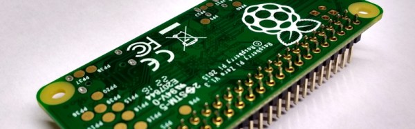
It’s obvious this was a controversial product, and maybe the Hackaday verdict had been a little summary based on the hammer aspect of the story. So to get further into what all the fuss had been about I ordered a Pi Zero and the solderless pin kit to try for ourselves.
What’s more expensive than a car and a less useful means of transportation? A 747 flight simulator built in a basement. There’s a project page where a few more details are revealed. There’s a 180 degree wrap-around screen for the main display, a glass cockpit, and the controls and gauges are ‘good enough’ to feel like the real thing. The simulator is running a highly customized version of FS9 (Microsoft’s flight sim from the year 2004).
For the last few years, Google has been experimenting with high altitude balloons delivering Internet to remote populations. This is Project Loon, and simply by the fact that Google hasn’t shuttered this Alpha-bit, we can assume the project is a success. A Project Loon balloon recently crashed in Panama, which means we can get an up-close look at the hardware. These balloon base stations are a lot bigger than you would think.
If you want to dial out from behind the great firewall of China, you’re probably going to use a VPN. Here’s an idea that doesn’t work as well as a VPN. Use an acoustic coupler with your iPhone. Will it work? Of course it will – modems have been standardized for fifty years. Will it work well? No, I can speak faster than 300 baud.
Do you sell on Tindie? We have a dog park. Tindie sellers around the world will be meeting up on Hackaday.io next Friday to discuss Tindie and Tindie-related activities. Join in!
A quick aside relating to Hackaday and Tindie swag. 1) The Tindie dog as a stuffed animal. 2) A Hackaday logo t-shirt where the skull is decorated like a Día de Muertos sugar skull. Pick one, leave your response in the comments.