First off, we’ll admit that there no real practical reason for wanting a wooden mouse – unless of course the cellulose rodent in question is the one that kicked it all off in “The Mother of All Demos” fifty years ago. Simply putting a shell around the guts of a standard wireless optical mouse is just flexing, but we’re OK with that.
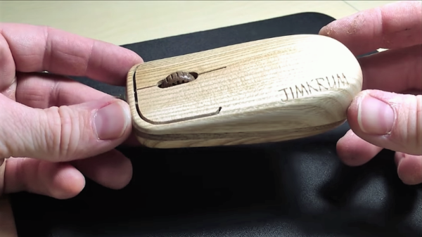
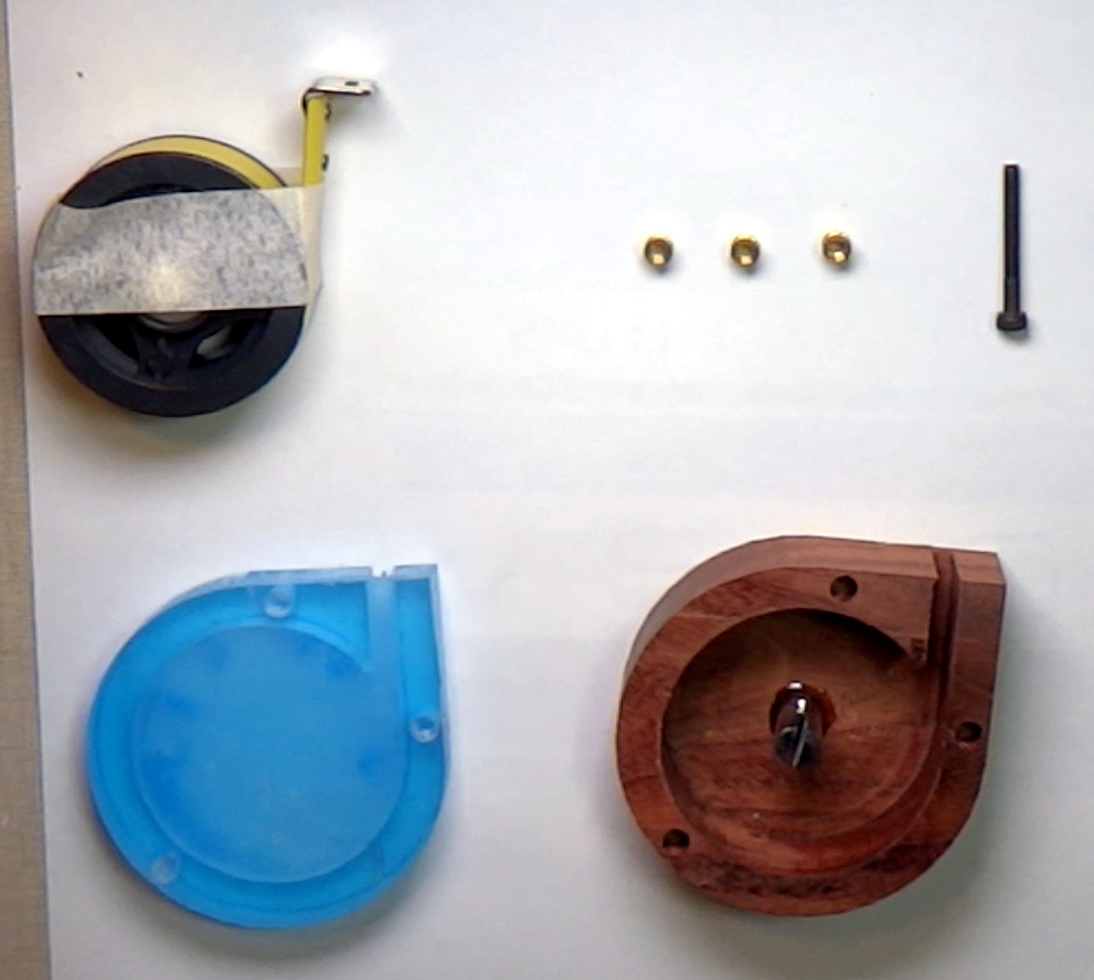
That said, [Jim Krum]’s design shows some impressive skills, both in the design of the mouse and the build quality of his machine. Starting with what looks like a block of white oak, [Jim] hogs out the rough shape of the upper shell and then refines it with a small ball-end mill before flipping it over to carve the other side. His registration seems spot on, because everything matches up well and the shell comes out to be only a few millimeters thick. The bottom plate gets the same treatment to create the complex shape needed to support the mouse guts and a battery holder. He even milled a little battery compartment cover. He used a contrasting dark wood for the scroll wheel and a decorative band to hold the top and bottom together and finished it with a light coat of sealer.
It’s a great look, and functional too as the video below reveals. We’ve seen a few other fancy mice before, like this wood and aluminum model or even one that would look at home on [Charles Babbage]’s desk.
Continue reading “Home-Brew CNC Router Mills A Wooden Mouse”
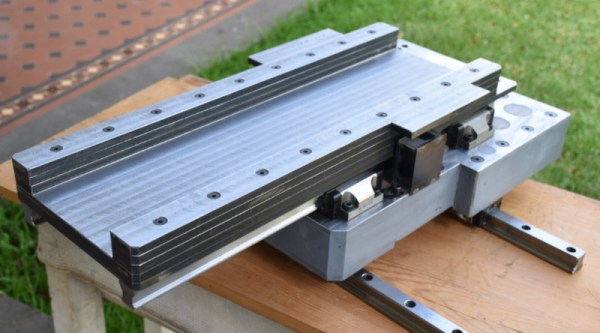
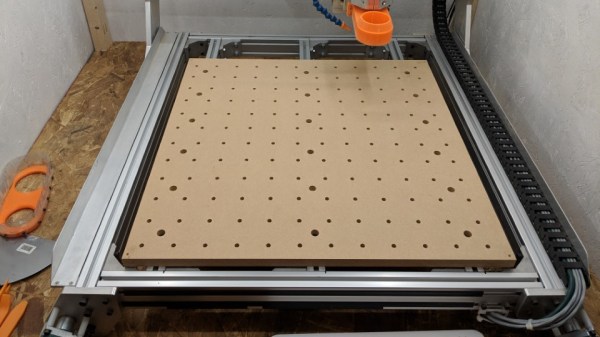
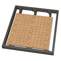 [Adam Haile] has been spending some time improving his CNC router and his latest change is


