Transformerless power supplies are showing up a lot here on Hackaday, especially in inexpensive products where the cost of a transformer would add significantly to the BOM. But transformerless power supplies are a double-edged sword. That title? Not clickbait. Poking around in a transformerless-powered device can turn your oscilloscope into a smoking pile or get you electrocuted if you don’t understand them and take proper safety precautions.
But this isn’t a scare piece. Transformerless designs are great in their proper place, and you’re probably going to encounter one someday because they’re in everything from LED lightbulbs to IoT WiFi switches. We’re going to look at how they work, and how to design and work on them safely, because you never know when you might want to hack on one.
Here’s the punchline: transformerless power supplies are safely useable only in situations where the entire device can be enclosed and nobody can accidentally come in contact with any part of it. That means no physical electrical connections in or out — RF and IR are fair game. And when you work with one, you have to know that any part of the circuit can be at mains voltage. Now read on to see why!
This Herald is in much better condition than my 12/50 was. Philafrenzy [CC BY-SA 4.0]What was your first car? Mine was a 1965 Triumph Herald 12/50 in conifer green, and to be frank, it was a bit of a dog.
The Triumph Herald is a small saloon car manufactured between about 1959 and 1971. If you are British your grandparents probably had one, though if you are not a Brit you may have never heard of it. Americans may be familiar with the Triumph Spitfire sports car, a derivative on a shortened version of the same platform. It was an odd car even by the standards of British cars of the 1950s and 1960s. Standard Triumph, the manufacturer, had a problem with their pressing plant being owned by a rival, so had to design a car that used pressings of a smaller size that they could do in-house. Thus the Herald was one of the last British mass-produced cars to have a separate chassis, at a time when all other manufacturers had produced moncoques for years.
My 12/50 was the sporty model, it had the high-lift cam from the Spitfire and a full-length Britax sunroof. It was this sunroof that was its downfall, when I had it around a quarter century of rainwater had leaked in and rotted its rear bodywork. This combined with the engine being spectacularly tired and the Solex carburetor having a penchant for flooding the engine with petrol made it more of a pretty thing to look at than a useful piece of transport. But I loved it, tended it, and when it finally died irreparably I broke it for parts. Since then I’ve had four other Heralds of various different varieties, and the current one, a 1960 Herald 948, I’ve owned since the early 1990s. A piece of advice: never buy version 0 of a car.
A few weeks back, we talked about the no-nos of running I²C over long wires. For prototyping? Yes! But for a bulletproof production environment, this practice just won’t make the cut. This month I plucked my favorite solution from the bunch and gave it a spin. Specifically, I have put together a differential I²C (DI²C) setup with the PCA9615 to talk to a string of Bosch IMUs. Behold: an IMU Noodle is born! Grab yourself a cup of coffee and join me as I arm you with the nuts and bolts of DI²C so that you too can run I²C over long cables like a boss.
What’s so Schnazzy about Differential Signals?
There’s a host of ways to make I²C’s communication lines more noise resistant. From all of the choices we covered, I picked differential signals. They’re simple, fairly standardized, and just too elegant to ignore. Let’s take a moment for a brief “differential-signals-101” lecture. Hopefully, you’re already caffeinated! Continue reading “An Introduction To Differential I²C”→
The four bar linkage is a type of mechanical linkage that is used in many different devices. A few examples are: locking pliers, bicycles, oil well pumps, loaders, internal combustion engines, compressors, and pantographs. In biology we can also find examples of this linkage, as in the human knee joint, where the mechanism allows rotation and keeps the two legs bones attached to each other. It is also present in some fish jaws that evolved to take advantage of the force multiplication that the four bar mechanism can provide.
How It Works
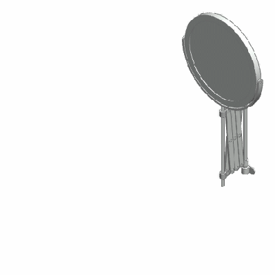
Deployable mirror with scissor linkages. By [Catsquisher] via Wikimedia CommonsThe study of linkages started with Archimedes who applied geometry to the study of the lever, but a full mathematical description had to wait until the late 1800’s, however, due to the complexity of the resulting equations, the study and design of complex linkages was greatly simplified with the advent of the digital computer.
Mechanical linkages in general are a group of bodies connected to each other to manage forces and movement. The bodies, or links, that form the linkage, are connected to each other at points called joints. Perhaps the simplest example is the lever, that consists of a rigid bar that is allowed to pivot about a fulcrum, used to obtain a mechanical advantage: you can raise an object using less force than the weight of the object.
Two levers can be connected to each other to form the four bar linkage. In the figure, the levers are represented by the links a (A-D) and b (B-C). The points A and B are the fulcrum points. A third link f (C-D) connects the levers, and the fourth link is the ground or frame g (A-B) where the mechanism is mounted. In the animation below, the input link a (the crank) performs a rotational motion driving the rocker rod b and resulting in a reciprocating motion of the link b (the rocker).
This slider-crank arrangement is the heart of the internal combustion engine, where the expansion of gases against a sliding piston in the cylinder drives the rotation of the crank. In a compressor the opposite happens, the rotation of the crank pushes the piston to compress the gas in the cylinder. Depending on how the mechanism is arranged, it can perform the following tasks:
convert rotational motion to reciprocating motion, as we just discussed above.
convert reciprocating motion to rotational motion, as in the bicycle.
constrain motion, e.g. knee joint and car suspension.
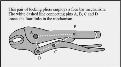
One interesting application of the four bar linkage is found in locking pliers. The B-C and C-D links are set at an angle close to 180 degrees. When force is applied to the handle, the angle between the links is less than 180 (measured from inside the linkage), and the resulting force in the jaws tries to keep the handle open. When the pliers snap into the locked position that angle becomes less than 180, and the force in the jaws keeps the handle in the locked position.
In a bicycle, the reciprocating motion of the rider´s legs is converted to rotational motion via a four bar mechanism that is formed by the two leg segments, the bicycle frame, and the crank.
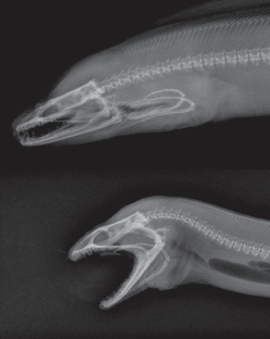
An example from nature, the Moray eel. Image from [Matthew West]As with many other inventions of humankind, we often find that nature has already come up with the same idea via evolution. The parrotfish lives on coral reefs, from which it feeds, and has to grind the coral to get to the polyps inside. For that job, they need a very powerful bite. The parrotfish obtains a mechanical advantage to the muscle force by using a four bar linkage in their jaws! Other species also use the same mechanism, one is the Moray eel, shown in the image, which has the very particular ability to launch its jaws up in the mouth to capture its prey, much like the alien from the film series.
The joints connecting the links in the linkage can be of two types. A hinged joint is called a revolute, and a sliding joint is called a prismatic. Depending on the number of revolute and prismatic joints, the four bar linkage can be of three types:
Planar quadrilateral linkage formed by four links and four revolute points. This is shown in the animation above.
Slider-crank linkage, formed by three revolute joints and a prismatic joint.
Double slider formed by two revolute joints and two prismatic joints. The Scotch yoke and the trammel of Archimedes are examples.
There are a great number of variations for the four bar linkage, and as you can guess, the design process to obtain the forces and movements that we need is not an easy task. An excellent resource for the interested reader is KMODDL (Kinematic Models for Design Digital Library) from Cornell University. Other interesting sites are the 507 mechanical movements, where you can find nice animations, and [thang010146]’s YouTube channel.
We hope to have piqued your curiosity in mechanical things. In these times of ultra fast developments in electronics, looking at the working of mechanisms that were developed centuries ago, but are still present and needed in our everyday lives can be a rewarding experience. We plan to work on more articles featuring interesting mechanisms so please let us know your favorites in the comments below.
In the last edition of Don’t Fear the Filter, we built up two examples of the simplest and most-used active filter of all time: the two-pole Sallen-Key lowpass. This time, we’re going to put two of these basic filter blocks in a row, and end up with a much sharper lowpass filter as well as a bandpass filter. For the bandpass, we’ll need to build up a quick highpass filter as well. Bonus!
I claimed last time that the Sallen-Key lowpass would cover something like 80% of your filtering needs. (And 72.4% of all statistics are totally made up!) These two will probably get you through another 10% or so. Honestly, I’ve never built a standalone active highpass, for reasons we’ll see below, but the active bandpass filter that we’re building it for is a great tool to have in your belt, especially for anything audio.
In the comments to our recent article about Wimshurst machines, we saw that some hackers had never heard of them, reminding us that we all have different backgrounds and much to share. Well here’s one I’m guessing even fewer will have heard of. It’s never even shown up in a single Hackaday article, something that was also pointed out in a comment to that Wimshurst article. It is the Lord Kelvin’s Water Dropper aka Lord Kelvin’s Thunderstorm, invented in the 1860s by William Thomson, 1st Baron Kelvin, the same fellow for whom the Kelvin temperature scale is named. It’s a device that produces a high voltage and sparks from falling drops of water.
In a recent article, I lamented my distaste for carrying on the classic amateur radio conversation — calling CQ, having someone from far away or around the block call back, exchange call signs and signal reports and perhaps a few pleasantries. I think the idle chit-chat is a big turn-off to a lot of folks who would otherwise be interested in the World’s Greatest Hobby™, but thankfully there are plenty of ways for the mic-shy to get on the air. So as a public service I’d like to go over some of the many digital modes amateur radio offers as a way to avoid talking while still communicating.

![This Herald is in much better condition than my 12/50 was. Philafrenzy [CC BY-SA 4.0]](https://hackaday.com/wp-content/uploads/2017/03/triumph_herald_southgate_london.jpg)


 In a bicycle, the reciprocating motion of the rider´s legs is converted to rotational motion via a four bar mechanism that is formed by the two leg segments, the bicycle frame, and the crank.