Once relegated to the proverbial Linux loving Firefox user, ad blocking has moved into public view among increased awareness of privacy and the mechanisms of advertising on the internet. At the annual family gathering, when That Relative asks how to setup their new laptop, we struggle through a dissertation on the value of ad blockers and convince them to install one. But what about mediums besides the internet? Decades ago Tivo gave us one button to jump through recorded TV. How about the radio? If available, satellite radio may be free of The Hated Advertisement. But terrestrial radio and online streams? [tomek] wasn’t satisfied with an otherwise sublime experience listening streaming Polish Radio Three and decided to build a desktop tool to detect and elide ads from the live audio stream.
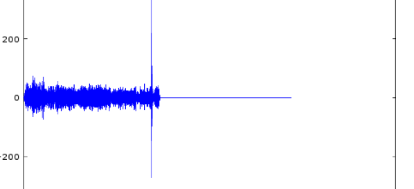
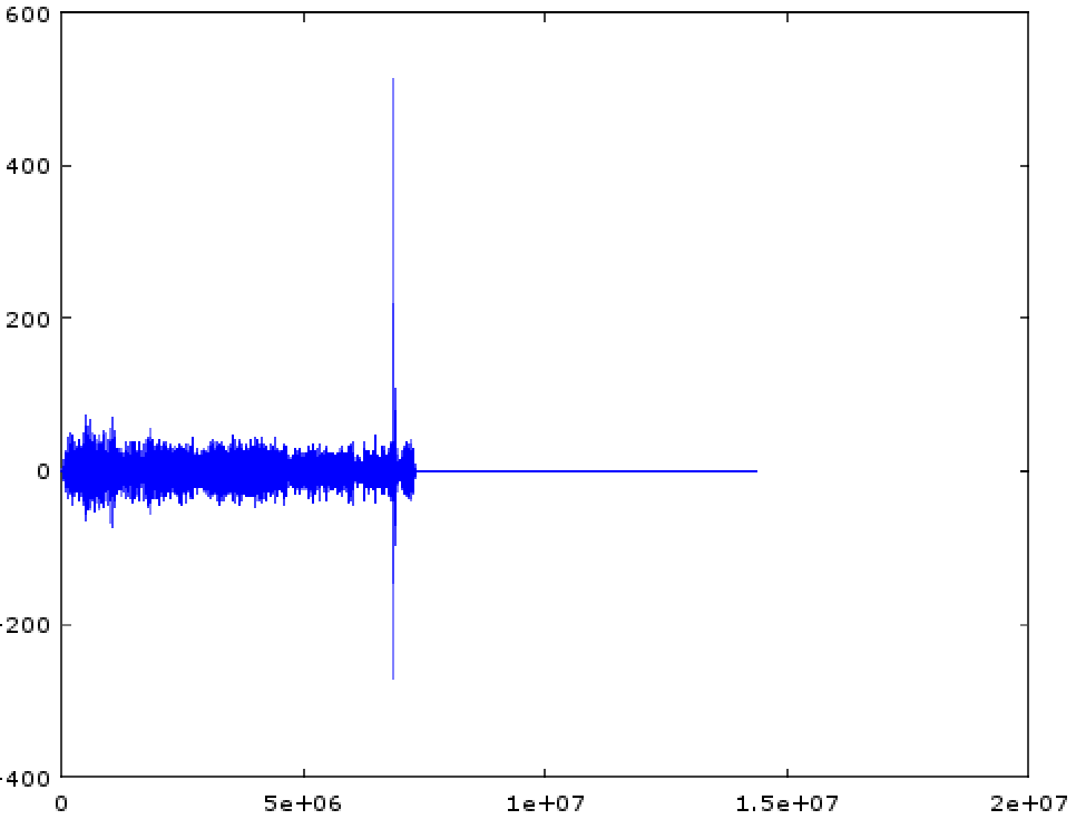 [tomek] was aware of this hip knowledge domain called Digital Signal Processing but hadn’t done any of it themselves. Like many algorithmic problems the first step was to figure out the fastest way to bolt together a prototype to prove a given technique worked. We were as surprised as [tomek] by how simple this turned out to be. Fundamentally it required a single function – cross-correlation – to measure the similarity of two data samples (audio files in this case). And it turns out that Octave provides it in the box. After snipping the start-of-ad jingle out of a sample file and comparing it to a radio program [tomek] got the graph at the left. The conspicuous spike is the location of the jingle in the audio file.
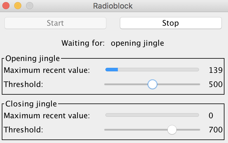 At this point all that was left was packaging it all into a one click tool to listen to the radio without loading an entire analysis package. Conveniently Octave is open source software, so [tomek] was able to dig through its sources until they found the bones of the critical xcorr() function. [tomek] adapted their code to pour the audio into a circular buffer in order to use an existing Java FFT library, and the magic was done. Piping the stream out of ffmpeg and into the ad detector yielded events when the given ad jingle samples were detected.
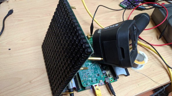
[tomek] packaged that tool into a standalone executable, but the gem here is the followup post. After removing ads in the online stream they adapted a RaspberryPi to listen to an FM receiver and remote control their Yamaha tuner over the network. So when the tuner is playing Radio Three the Pi notices and ducks the audio appropriately to avoid those pesky ads. Video of this after the break.
Continue reading “Cross-Correlation Makes Quick Work Of Ads”