One of the best ways to teach electronics and programming is with hands-on learning. Get the concepts off the computer screen and out into the real world. Students of all ages have been learning with robots for decades. Many older Hackaday readers will remember the turtle robots. These little ‘bots would drive around drawing shapes created in the logo programming language. This week’s Hacklet is all about the next generation of robots that teach electronics, mechanics, programming, and of course, hacking. So let’s check out some of the best educational robot projects on Hackaday.io!
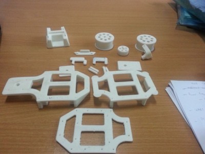
 We start with [Tom Van den Bon] and Edubot Controller (Benny). Buying one or two robots can get expensive. Equipping a classroom full of them can break the bank. [Tom] is hoping to make robots cheaper and more accessible with Edubot, his entry in the 2016 Hackaday prize. Edubot rides on a 3D printed frame with low-cost gear motors for a drive system. Edubot’s brain is an STM32F042, a low-cost ARM processor from ST micro. The micro and motor drives are integrated into a custom board [Tom] designed. He’s has even begun creating lesson plans so students of various ages and skill levels can participate and learn.
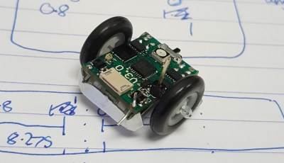 Next up is [Joshua Elsdon] with Micro Robots for Education. Big robots can be intimidating. They can also cause some damage when hardware and software created by budding engineers doesn’t operate as expected. Tiny robots though, are much easier to wrangle. [Joshua ] may have taken tiny to an extreme with these robots. Each robot is under 2 cm square. The goal is for each one to cost less than £10 to produce. These micro bots have big brains with their ATmega328P micro controllers. [Joshua] is currently trying to figure out a low-cost way to produce wheels for these robots.
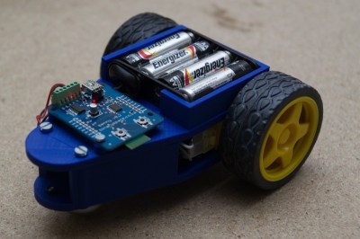
Next we have [shamylmansoor] with 3D printed mobile robot for STEM education. Robots are expensive, and international shipping can make them even more expensive. [Shamyl] is shooting for a robot which can be made locally in Pakistan. 3D printing is the answer. The robot’s chassis can be printed on any FDM printer. Wheels,and tires are low-cost units. Motors are RC servos modified for continuous rotation. The brains of the robot is an Arduino Mega 2560, which should provide plenty of inputs for sensors. [Shamyl] even included a solderless breadboard so students can prototype circuits and sensors right on the robot’s body.
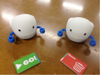 Finally we have [Rodolfo] with Plobot. Plobot is a robot designed for the youngest hackers – those from four to seven years old. [Rodolfo] designed Plobot to be programmed with RFID cards. Each card contains a command such as move forward, turn, start, and reset. Many of the language mechanics are inspired by the Scratch programming language. Plobot’s processor is a Sanguino, running [Rodolfo’s] custom code. An ESP8266 allows Plobot to be connected to the outside world via WiFi. [Rodolfo] has even created a custom over the air update system for Plobot’s firmware. Plobot has already been tested with students, where it made a great showing. We’re hoping both [Rodolfo] and Plobot do well in the 2016 Hackaday Prize!
If you want more mind hacking goodness, check out our brand new educational robot list! Did I miss your project? Don’t be shy, just drop me a message on Hackaday.io. That’s it for this week’s Hacklet, As always, see you next week. Same hack time, same hack channel, bringing you the best of Hackaday.io!


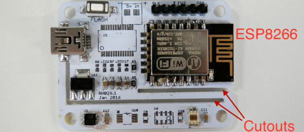
 Next came the clever bit. [Richard] put cutouts into the board to hopefully stop the flow of heat from the ESP8266 module to the temperature sensor. Again, he found that the board heats up by around four degrees Celcius or nine degrees Farenheit. That’s a horrible result in any units.
 Fail of the Week is a Hackaday column which celebrates failure as a learning tool. Help keep the fun rolling by writing about your own failures and