As a society, we’ve become accustomed to always-on high-speed data connections, whether we’re at home on the computer or out and about with a mobile device. But what happens if a natural disaster knocks out the local infrastructure? Sure some people will be able to fire up their radio if they need to reach out and touch someone, but even among hackers, hams are a minority. What we really need is a backup Internet.
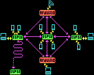
The team behind the CellSol project hopes to show that building a volunteer-operated distributed communications network is not only within the capabilities of the hacker community but probably much easier and cheaper to do than you might think. Each node in the network, known as a Pylon in CellSol parlance, can shuttle data between the LoRa backbone and WiFi-enabled devices like smartphones and computers. Once the network is up and running, users don’t need any special hardware or software to use it.
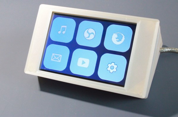
 Now to be clear, nobody is talking about surfing the web here. When a user connects to one of the ESP32 Pylons, they’ll be able to access a simplistic chat system through their browser. If the Pylon has an active Internet connection the chat can be bridged to an IRC channel. Without Internet connectivity, the pylon will simply give users on the CellSol network a means to communicate among each other. To keep things simple there’s no user names, private messages, or encryption. This is bare-bones, end-of-the-world style communication.
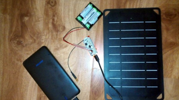
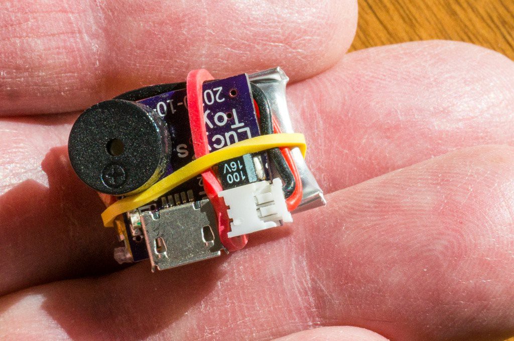
Want to join the CellSol revolution? All you really need is an ESP32, a LoRa radio, and the open-source firmware. If you get something like the Heltec LoRa 32 development board, you don’t even need to solder anything together. Just flash the board and go. Once you have a few Pylons going, you can also put together a cheap repeater node using a LoRa equipped Arduino. Both devices are small and energy efficient enough that they could easily be battery or solar powered. As you can see in the video after the break, the team even envisions a future where they could be dropped off in public areas via drone.
This isn’t the first time we’ve seen the ESP32 used to establish an off-grid LoRa communications network, and like those previous attempts, it’s usefulness will largely depend on how many people you can convince to set up their own nodes and repeaters. But if you’ve got some open minded friends who live relatively close by, this could be a great way to have a little chat.
Continue reading “IRC Over LoRa, For When Things Really Go South” →