Morphing Digital Clock Will Show You A Good Time

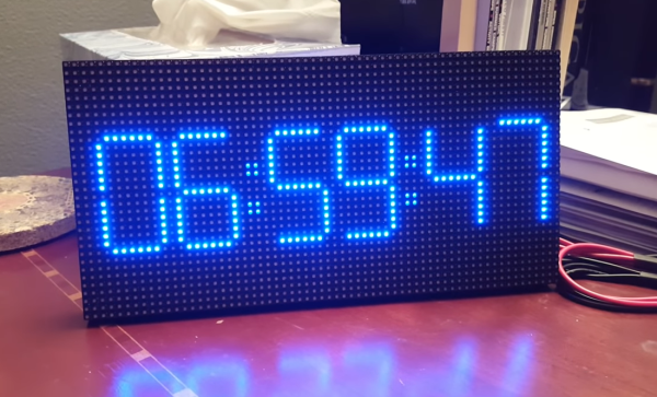
A few weeks ago, [HariFun] set out to emulate a 7-segment display with an LED matrix. Seems easy enough, right? Right. He also wanted to come up with a new way to transition between digits, which is a much harder task. But he did it, and it’s really cool. At a viewer’s suggestion, [Hari] used the transition as the basis for a mesmerizing clock that brings the smooth sweep of an analog second-hand into the digital age.

This is the coolest way to watch the time pass since the hourglass. You can almost hear the light move as one digit slides into the next. Each transition is totally unique, so depending on the digit this involves one or more vertical segments sliding from right to left, or multiple segments moving in a counter-clockwise circle.

You too can watch time glide by with little more than a 64×32 RGB LED matrix, a NodeMCU, and [Hari]’s digit transition code. It only costs about $25 to build, and you really can’t beat the quality of instruction he’s put together. Take a second or two and check it out after the break.

If you prefer OLEDs and vertical transitions, there’s a clock for that, too.

Continue reading “Morphing Digital Clock Will Show You A Good Time”

Vintage Headphones Bluetooth Conversion Goes The Extra Mile

[KaZjjW] wanted to retrofit a pair of nicely styled vintage headphones to be able to play wirelessly over Bluetooth. In principle this is an easy task: simply stick a Bluetooth audio receiver on the line-in, add a battery, and you’re all set. However, [KaZjjW] wanted to keep the aesthetic changes to the headphones at an absolute minimum, retaining the existing casing and volume control, whilst cramming the electronics entirely inside and out of sight.

With the inherent space constraints inside the cups of the headphones, this proved to be quite a challenge. The existing volume potentiometer which hung half outside the case was remounted on an ingenious hinge made of two PCBs, with the pot floating next to a surface mounted switch. This allowed it to not only control the volume, but also act as an on/off switch for the Bluetooth. The only other existing cuts in the casing were a circular hole for the audio cable, and a slit for the cable strain relief. These worked perfectly for an LED status indicator and micro-USB battery charging.

The main chip used for receiving audio over Bluetooth was the BM62 by Microchip. It’s a great all-in-one solution for this kind of project as it has built-in battery charging, an on-board DAC and audio amp, as well as a serial control interface. In part 2 of the project log, the process of programming the BM62 was documented, and it was painful – it’s a shame that the software support lets it down. But a hacker will always find a way, and we’ve seen some pretty neat hacks for reprogramming existing chips in off-the-shelf Bluetooth headphones.

Two PCBs for the pot button hinge, one for the LED and micro-USB connector, as well as one for the Bluetooth receiver and a PIC. That’s four PCBs in a pretty small space, enabled by some commendable design effort both electronically and mechanically. It certainly paid off, as the finished product looks very slick.

Continue reading “Vintage Headphones Bluetooth Conversion Goes The Extra Mile”

A Peek Into A Weed-Eating Robot’s Test Fixtures

When it comes to production, fast is good! But right the first time is better. Anything that helps prevent rework down the line is worth investing in. Some of the best tools to catch problems are good test fixtures. The folks at Tertill (a solar-powered robot for killing weeds that kickstarted last year) took the time to share two brief videos of DIY test fixtures they use to test components before assembly.

The videos are short, but they demonstrate all the things that make a good test: on the motor tester there are no connectors or wires to fiddle with, the test starts automatically, and there is clear feedback via prominent LEDs. The UI board tester also starts automatically and has unambiguous LED feedback, and sports a custom board holder with a recess just the right shape for the PCB. Once the board is in, the sled is pushed like a drawer to make contact with the test hardware and begin the test. The perfectly formed recesses in both units serve another function as well; they act as a go/no-go test for the physical shape of the components and contacts being tested.

Both videos are embedded below; and while there isn’t much detail on the actual test hardware, we do spy a Raspberry Pi and at least two Adafruit logos among other hacker-familiar elements like laser-cut acrylic, 3D printed plastic, pogo pins, and a PVC junction box.

Continue reading “A Peek Into A Weed-Eating Robot’s Test Fixtures”

Junk Bin Self Balancing Bot With ESP8266

As we all know, sometimes the projects we plan simply never materialize. You have an idea, maybe even buy some of the parts you need, and then…nothing. Maybe you changed your mind, or maybe the idea was never that good to begin with. In any event, time marches on, the parts pile up, and the ideas come and go. Such is the life of the hacker.

[Andrius Mikonis] writes in to tell us how his graveyard of abandoned projects ended up providing exactly what he needed to embark on a project he’s been fascinated with for years: the two-wheel self balancing robot. He started with a motor and wheel set that was originally intended to be part of a rover, added an accelerometer, and tied the whole thing together with an ESP-01 he had lying around. The final result certainly looks the part, and goes to show that projects don’t always need to be 1000 hour labors of love to accomplish their goals.

The construction of this little bot is simple in the extreme. A piece of plywood makes up the primary structure, with the wheels glued to the bottom and the electronics taking up residence in the top. It’s powered by two lithium battery cells that were salvaged out of an old laptop, with a DC-DC buck converter to provide a stable 3.3 VDC for the ESP-01 and MPU6050 accelerometer. To control the motors themselves, [Andrius] is using a cheap L293 controller that he found on eBay.

For interactive control, [Andrius] is making use of the ESP’s Wi-Fi to provide a web-based interface. This lets you control the bot from essentially any device that has a browser, rather than having to use a dedicated hardware transmitter.

Self-balancing robots of various levels of complexity are a relatively common project in the hacker world. There’s just something magical about the way they scoot around, seeming to defy gravity.

ESP8266 Keeps Tabs On The Kid’s Tablets

Assuming you have a child and it’s no longer womb-bound, there’s a fairly high chance they’ve already had some experience with the glowing beauty that is the LCD display; babies of only a few months old are often given a tablet or smartphone to keep them occupied. But as the child gets to the age where they are capable of going outside or doing something more constructive, staring slack-jawed and wide-eyed at their tablet becomes a concern for many parents.

[Richard Garsthagen] is one such parent. He wanted a way to monitor and control how much time his children were using their iPad, so he came up with an automated system based on the ESP8266. Not only does it keep track of how long the tablet is being used, it even includes a reward system which allows the parent to add extra usage time for good behavior.

At the most basic level, the device is a sort of “holster” for the child’s tablet. When the tablet is placed in the slot, it presses a microswitch at the bottom of the cavity which stops the timer. When the switch is open, the LED display on the front of the device counts down, and the ESP8266 pushes notifications about remaining time to the child’s device via IFTTT.

Time can be added to the clock by way of RFID cards. The cards are given out as a reward for good behavior, completion of chores, etc. The child only needs to pass the card in front of the system to redeem its value. Once the card has been “spent”, the parent can reset it with their own special card.

It’s a very slick setup, making perfect use of the ESP8266. Reading the RFID cards, updating the timer, and using IFTTT’s API keeps the little board quite busy; [Richard] says it’s completely maxed out.

You might be wondering what happens when the clock reaches zero. Well, according to the video after the break…nothing. Once the time runs out, a notification simply pops up on the tablet telling them to put it away. Some might see this as a fault, but presumably it’s the part of the system where humans take over the parenting and give the ESP8266 a rest.

This isn’t the first time we’ve seen a microcontroller used to get the little hackers on schedule. At least (so far) none of them have gone full Black Mirror and started tracking when the kiddos are watching it.

Continue reading “ESP8266 Keeps Tabs On The Kid’s Tablets”

The Smaller, Tinier Arduino Platform

While many of the Arduino platforms are great tools for gaining easy access to microcontrollers, there are a few downsides. Price and availability may be the highest on the list, and for those reasons, some have chosen to deploy their own open-source Arduino-compatible boards.

The latest we’ve seen is the Franzininho, an Arduino Gemma-like board that’s based on the ATtiny85, a capable but tiny microcontroller by Atmel in a compact 8-pin configuration. This board has everything the Gemma has, including a built-in LED and breakout pins. One of the other perks of the Franzininho over the Gemma is that everything is based on through-hole components, making the assembly much easier than the surface mount components of the Gemma.

It’s worth noting that while these boards are open source, the Arduinos are as well. It’s equally possible to build your own 100% identical Arduino almost as easily. If you want more features, you can add your own by starting from one of these platforms and do whatever you want with it, like this semi-educational Atmel breakout board.

Thanks to [Clovis] for the tip!

The A To Z Of Building Your Own Keyboard

We’ve featured a number of people who’ve taken the plunge and created their own customized keyboard; at this point it’s safe to say that there’s enough information and source code out there that anyone who’s looking to build their own board won’t have much trouble figuring out how to do so. That being said, it’s nice to have a comprehensive at a process from start to finish. Why sift through forum posts and image galleries looking for crumbs if you don’t have to?

That’s precisely what makes this write-up by [Maarten Tromp] so interesting. He walks the reader through every step of the design and creation of his customized keyboard, from coming up with the rather unique layout to writing the firmware for its AVR microcontroller. It’s a long read, filled with plenty of tips and tricks from a multitude of disciplines.

After looking at other custom boards for inspiration, [Maarten] used OpenSCAD to create a 3D model of his proposed design, and had it printed at Shapeways. His electronics are based around an Atmel ATMega328P using vUSB, and Microchip MCP23017 I/O expanders to connect all the keys. He wrapped it all up by designing a PCB in gEDA PCB and having it sent off for production. As a testament to his attention to detail, everything mated up on the first try.

[Maarten] is happy with the final product, but mentions that in a future revision he would like to add RGB lighting and use a microcontroller that has native USB support. He’d also like to drop the I/O expanders and switch over to Charlieplexing for the key matrix.

From uncommon layouts to diminutive technicolor beauties, it seems there’s no end of custom keyboards in sight. We aren’t complaining.