Performing music in open spaces can be a real challenge. The acoustics of the space can play spoil-sport. Now imagine trying to play an instrument spread out over tens of kilometres. The folks at [LimbicMedia] wrote in to tell us about the project they worked on to build the The World’s Largest Musical Instrument.
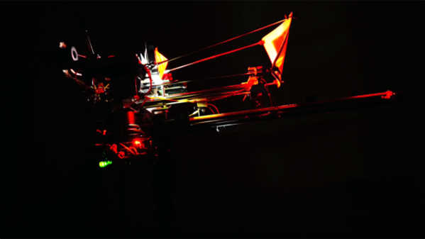
The system consists of wirelessly controlled air horns deployed at remote locations. Each air horn is self contained, driven by a supply of compressed air from a scuba diving tank and battery powered electronics. The wireless link allows the air horns to be placed up to 10kms away from the base station. Each air horn is tuned to a specific note of the piano keyboard which, in turn, is configured to transmit its note data to the air horns.
![]() Currently, they have built 12 air horns, enough to let them play the Canadian and British anthems. The horns are built out of PVC piping and other off-the-shelf plastics with the dimensions of the horn determining its note. The setup was installed and performed at the Music by the Sea festival recently, by mounting the air horns on 12 boats which were stationed out at Sea in the Bamfield Inlet in
Currently, they have built 12 air horns, enough to let them play the Canadian and British anthems. The horns are built out of PVC piping and other off-the-shelf plastics with the dimensions of the horn determining its note. The setup was installed and performed at the Music by the Sea festival recently, by mounting the air horns on 12 boats which were stationed out at Sea in the Bamfield Inlet in Eastern Western Canada. But that was just a small trial. The eventual plan is to set up air horns all around Canada, and possibly other places around the world, and synchronise them to play music simultaneously, to commemorate the 150th Canada Day celebrations in 2017.
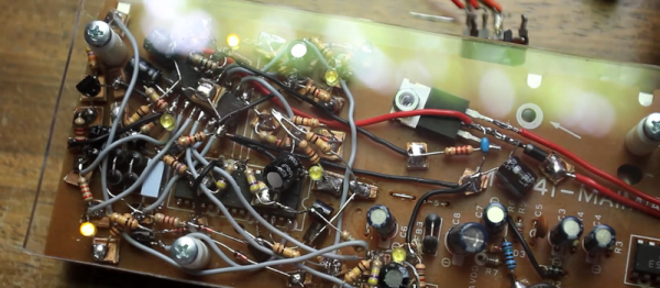
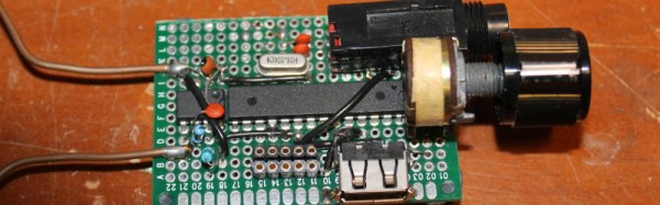
There aren’t many details shared about the hardware, but it’s not too difficult to make some guesses. A micro-controller to operate the air solenoid, long range radio link to connect all the air horns to the base station, and another controller to detect the key strokes on the Piano. The limiting issue to consider with this arrangement is the spatial separation between the individual air horns. Sound needs about 2.9 seconds to travel over a kilometer. As long as all the air horns are at approximately the same distance from the audience, this shouldn’t be a problem. See how they did in the video after the break. We do know of another project which handled that problem brilliantly, but we’ll leave the details for a future blog post.
This isn’t the first time [LimbicMedia] was commissioned to create audio-visual public installations. A couple of years back they built this Sound Reactive Christmas Tree in Victoria, British Columbia.


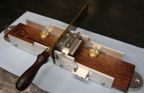
 Cutting the slots in a guitar’s neck for the frets requires special tooling, and [Gord]’s contribution to his friend’s recent dive into lutherie was