When it comes to our analog designs, op-amps tend to be just another jellybean part. We tend to spec whatever does the job, and don’t give much of a thought as to the internals. And while it doesn’t make much sense to roll your own op-amp out of discrete components, that doesn’t mean there isn’t plenty to be learned from doing just that.
While we’re more accustomed to seeing [Mitsuru Yamada]’s digital projects, he’s no stranger to the analog world. In fact, this project is a follow-on to his previous bipolar transistor op-amp, which we featured back in 2021. This design features MOSFETs rather than BJTs, but retains the same basic five-transistor topology as the previous work, with a differential pair input stage, a gain stage, and a buffer stage. Even the construction of the module is similar, using his trademark perfboard and ultra-tidy wiring.
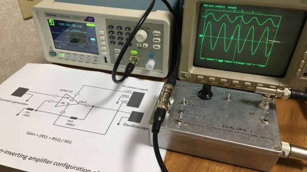
Also new is a flexible evaluation unit for these discrete op-amp modules. This very sturdy-looking circuit provides an easy way to configure the op-amp for testing in inverting, non-inverting, and transimpedance mode, selecting from a range of feedback resistors, and even provides a photodiode input. The video below shows the eval unit in action with the CMOS module, as well as highlights the excellent construction [Mitsuru Yamada] is known for.
Looking for some digital goodness? Check out the PERSEUS-8, a 6502 machine we wish had been a real product back in the day.
Continue reading “Op-Amp Challenge: MOSFETs Make This Discrete Op Amp Tick”
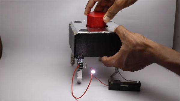


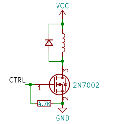 Perhaps, that’s the single most popular use for an NPN transistor – driving coils, like relays or solenoids. We are quite used to driving relays with BJTs, typically an NPN – but it doesn’t have to be a BJT, FETs often will do the job just as fine! Here’s an N-FET, used in the exact same configuration as a typical BJT is, except instead of a base current limiting resistor, we have a gate-source resistor – you can’t quite solder the BJT out and solder the FET in after you have designed the board, but it’s a pretty seamless replacement otherwise. The freewheel (back EMF protection) diode is still needed for when you switch the relay and the coil produces wacky voltages in protest, but hey, can’t have every single aspect be superior.


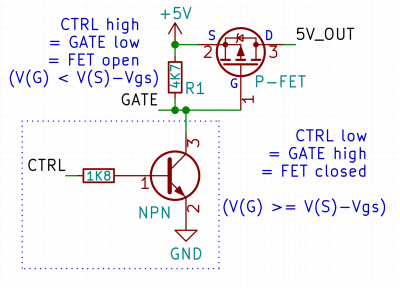 Here’s a simple FET circuit that lets you switch power to, say, a USB port, kind of like a valve that interrupts the current flow. This circuit uses a P-FET – to turn the power on, open the FET by bringing the GATE signal down to ground level, and to switch it off, close the FET by bringing the GATE back up, where the resistor holds it by default. If you want to control it from a 3.3 V MCU that can’t handle the high-side voltage on its pins, you can add a NPN transistor section as shown – this inverts the logic, making it into a more intuitive “high=on, low=off”, and, you no longer risk a GPIO!


