We’ve seen a number of projects over the years that let you create custom enclosures using OpenSCAD, and for good reason. The parametric CAD tool is ideal for generating 3D models based on user-adjustable variables, and if you leverage its integrated Customizer, producing a bespoke box is as easy as moving some sliders around. The resulting files get sent off to the 3D printer, and you’re set. But what if you’re looking for a custom enclosure that’s not so…plastic?
In that case, AlClosure by [0xPIT] might be the answer. Rather than generating STL files intended for your 3D printer, the code is written to help you design an enclosure made from aluminum sheets. The top and bottom panels are intended to be cut from 1.5 mm – 2.5 mm sheets, while the sides are made from thicker 5 mm – 8 mm stock to accept a machined pocket that holds the front and rear inserts.
 Since it’s OpenSCAD, much of the design is governed by variables which you can tweak. Obviously the outside dimensions of the enclosure can be changed in a flash, but it’s just as easy to modify the thickness of the aluminum sheet being used, or the size of the screw holes. [0xPIT] has also done a great job of documenting the code itself, so you’ll know exactly what you’re modifying.
Obviously, you’ll need the ability to cut and machine aluminum to actually utilize this project. The code itself is really just a way to conceptualize the design and get your dimensions figured out ahead of time. But as we were recently reminded by the keynote presentation [Jeremy Fielding] gave at the 2021 Remoticon, this sort of early prototyping can often save you a lot of headaches down the line.


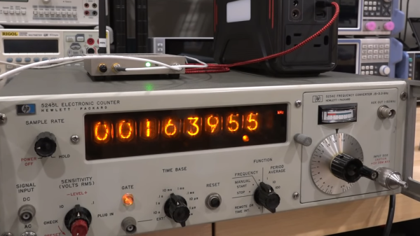
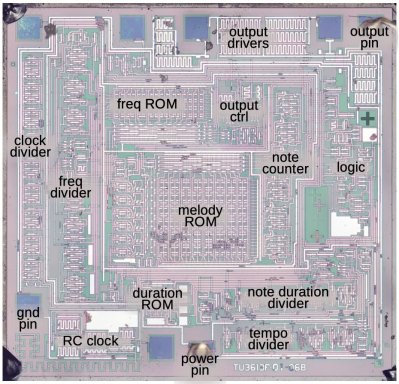 The surprise in this age of ubiquitous microcontrollers is that this is not a smart device; instead it’s a single-purpose logic chip whose purpose is to step through a small ROM containing note values and durations, driving a frequency generator to produce the notes themselves. The frequency generator isn’t the divider chain from the RC oscillator that we might expect, instead it’s a shift register arrangement which saves on the transistor count.