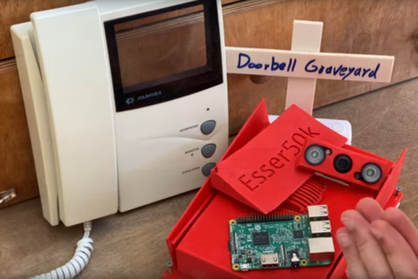
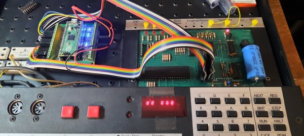
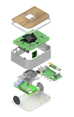
A Mostly Fair Deal For All With A Raspberry Pi

To be a professional card dealer takes considerable skill, something that not everybody might even have the dexterity to acquire. Fortunately even for the most ham-fisted of dealers there’s a solution, in the form of the Dave-O-matic, [David Stern]’s automated card dealer using a Raspberry Pi 4 with a camera and pattern recognition.

It takes the form of a servo-controlled arm with a sucker on the end, which is able to pick up the cards and present them to the camera. They can then be recognized by value, and pre-determined hands can be dealt or alternatively a random hand. It seems that the predetermined hands aren’t an aid in poker cheating, but a part of the bridge player’s art. You can see it in action in the video below the break.

We like the project, but sadly at this point we must take [Dave] to task, because while tantalizing us with enough detail to get us interested he’s slammed the door in our faces by failing to show us the code. it would be nice to think that the clamor from disaffected Hackaday readers might spur him into throwing us a crumb or two.

It probably won’t surprise you to find that this isn’t the first Raspberry Pi to find itself dealing cards.

Continue reading “A Mostly Fair Deal For All With A Raspberry Pi”

Pico Makes Capable Logic Analyzer

A common enough microcontroller project is to create some form of logic analyzer. In theory, it should be pretty easy: grab some digital inputs, store them, and display them. But, of course, the devil is in the details. First, you want to grab data fast, but you also need to examine the trigger in real time — hard to do in software. You may also need input conditioning circuitry unless you are satisfied with the microcontroller’s input characteristics. Finally, you need a way to dump the data for analysis. [Gusmanb] has tackled all of these problems with a simple analyzer built around the Raspberry Pi Pico.

On the front and back ends, there is an optional board that does fast level conversion. If you don’t mind measuring 3.3 V inputs, you can forego the board. On the output side, there is custom software for displaying the results. What’s really interesting, though, is what is in between.

The simple PCB is completely optional.

The Pico grabs 24 bits of data at 100 MHz and provides edge and pattern triggers. This is impressive because you need to look at the data as you store it and that eats up a few instruction cycles if you try to do it in software, dropping your maximum clock rate. So how does this project manage it?

It uses the Pico’s PIO units are auxiliary dedicated processors that aren’t very powerful, but they are very fast and deterministic. Two PIO instructions are enough to handle the work for simple cases. However, there are two PIOs and each has four separate state machines. It still takes some work, but it is easier than trying to run a CPU at a few gigahertz to get the same effect. The fast trigger mode, in particular, abuses the PIO to get maximum speed and can even work up to 200 MHz with some limitations.

If you want to try it, you can use nothing more than a Pico and a jumper wire as long as you don’t need the level conversion. The project page mentions that custom software avoids using OpenBench software, which we get, but we might have gone for Sigrok drivers to prevent having to reinvent too many wheels. The author mentions that it was easier to roll your own code than conform to a driver protocol and we get that, too. Still, the software looks nice and even has an SPI protocol analyzer. It is all open source, so if you want other protocols before the author gets to them, you could always do it yourself.

If you do want a Pico and Sigrok, we’ve covered a project that does just that. Most of the logic analyzers we use these days we build into our FPGA designs.

Classic Amp Revived With A Pi

Guitar amplifiers have a hard life, and as anyone who’s run a venue can tell you, they often have significant electrical issues after a life on the road. [Dsagman] had a Vox amplifier with fried internals, and rather than repair the original he rebuilt it with a Raspberry Pi inside to provide a fully-loaded array of effects.

Though the subject is the Vox, it’s best to see this as more a tale of how to create a guitar effect array in a Pi than specifically put it in an amplifier. The Pi has an audio board and an MCP3008 ADC added to it, and using those two it takes its inputs from a series of potentiometers and process the audio passing through the audio board. In addition there are a series of LED indicators and an LED bar graph to keep the user in touch with what’s going on.

The whole lot is nicely integrated in the VOX case with all the potentiometers on an aluminium panel. He discusses amplifier choice, but as you might expect the final choice is a Class D module. All in all an amp many readers would probably go for.

As long-time readers will remember, guitar effects have made quite a few appearances around here. Continue reading “Classic Amp Revived With A Pi”

PlayStation 2 Gets A Seamless Media Center Makeover

We often see Raspberry Pi boards of various flavors stuck inside vintage computers and the like. [El Gato Guiri] has instead installed one inside a PlayStation 2 Slim, and rather artfully at that. The result is a tidy little media center device.

Pretty tidy, right? All those ports work! Okay, not the memory card slots. But everything else!

The PlayStation 2 was gutted, with a Raspberry Pi 3B installed inside. The original ports on the back, including the USB and Ethernet port, were then wired up to the Pi to make them fully functional. A slot was then cut into the back to allow the HDMI port to be hooked up. The front USB ports work, too, and the optical drive was removed to make way for a 2 TB Toshiba external drive. Adapters are used to make the controller ports work, as well. Finally, a Noctua fan was installed atop the Pi to make sure it never gets too hot.

Whether it’s for watching movies or playing emulated games with the PS2 controllers, the little media center build is sure to do well.

We’ve seen Raspberry Pis stuck in everything from laptops to monitors, as well as plenty of retro hardware too. When a piece of hardware is dead and gone, a Raspberry Pi can be a great way to breathe new life into an attractive old case!

Sketch of the two proprietary carriers showing their differences - one of them has a cutout under the antenna, while the other one does not.

Design Your CM4 Carrier With WiFi Performance In Mind

The Raspberry Pi Compute Module 4 has a built-in WiFi antenna, but that doesn’t mean it will work well for you – the physical properties of the carrier board impact your signal quality, too. [Avian] decided to do a straightforward test – measuring WiFi RSSI changes and throughput with a few different carrier boards. It appears that the carriers he used were proprietary, but [Avian] provides sketches of how the CM4 is positioned on these.

There’s two recommendations for making WiFi work well on the CM4 – placing the module’s WiFi antenna at your carrier PCB’s edge, and adding a ground cutout of a specified size under the antenna. [Avian] made tests with three configurations in total – the CMIO4 official carrier board which adheres to both of these rules, carrier board A which adheres to neither, and carrier board B which seems to be a copy of board A with a ground cutout added.

Graph plotting WiFi RSSI for each of the three carriers in each of the six locations. CMIO4 consistently outperforms both, while carrier B outperforms the carrier A, but by a more narrow margin.After setting up some test locations and writing a few scripts for ease of testing, [Avian] recorded the experiment data. Having that data plotted, it would seem that, while presence of an under-antenna cutout helps, it doesn’t affect RSSI as much as the module placement does. Of course, there’s way more variables that could affect RSSI results for your own designs – thankfully, the scripts used for logging are available, so you can test your own setups if need be.

If you’re lucky to be able to design with a CM4 in mind and an external antenna isn’t an option for you, this might help in squeezing out a bit more out of your WiFi antenna. [Avian]’s been testing things like these every now and then – a month ago, his ESP8266 GPIO 5V compatibility research led to us having a heated discussion on the topic yet again. It makes sense to stick to the design guidelines if WiFi’s critical for you – after all, even the HDMI interface on Raspberry Pi can make its own WiFi radio malfunction.

picture of a brambling (a small bird), with "BirdNET-Pi" written above it

Neural Network Identifies Bird Calls, Even On Your Pi

Recently, we’ve stumbled upon the extensive effort that is the BirdNET research platform. BirdNET uses a neural network to identify birds by the sounds they make, and is a joint project between the Cornell Lab of Ornithology and the Chemnitz University of Technology. What strikes us is – this project is impressively featureful and accessible for a variety of applications. No doubt, BirdNET is aiming to become a one-stop shop for identifying birds as they sing.

There’s plenty of ways BirdNET can help you. Starting with likely the most popular option among us, there are iOS and Android apps – giving the microphone-enabled “smart” devices in our pockets a feature even the most app-averse hackers can respect. However, the BirdNET team also talks about bringing sound recognition to our browsers, Raspberry Pi and other SBCs, and even microcontrollers. We can’t wait for someone to bring BirdNET to a RP2040! The code’s open-source, the models are freely available – there’s hardly a use case one couldn’t cover with these.

Screenshot of the BirdNET-Pi interface, showing a chart of bird chirp occurences, and a spectrogram below itAbout that Raspberry Pi version! There’s a sister project called BirdNET-Pi – it’s an easy-to-install software package intended for the Raspberry Pi OS. Having equipped your Pi with a USB sound card, you can make it do 24/7 recording and analysis using a “lite” version of BirdNET. Then, you get a web interface you can log into and see bird sounds identified in real-time. Not just that – BirdNET-Pi also processes the sounds and creates spectrograms, keeps the sound in a database, and can even send you notifications.

The BirdNET-Pi project is open, too, of course. Not just that – the BirdNET-Pi team emphasizes everything being fully local, unless you choose otherwise, and perhaps decide to share it with others. Many do make their BirdNET-Pi instances public, and there’s a lovely interactive map that shows bird sounds all across the world!

BirdNET is, undoubtedly, a high-effort project – and a shining example of what a dedicated research team can do with a neural network and an admirable goal in mind. For many of us who feel joy when we hear birds outside, it’s endearing to know that we can plug a USB sound card into our Pi and learn more about them – even if we can’t spot them or recognize them by sight just yet. We’ve covered bird sound recognition on microcontrollers before – also using machine learning.

LMN-3: Putting The ‘OP’ In Open Source Synthesizers

Some projects you come across simply leave you in awe when you look at the thought and the resulting amount of work that went into it, not only for the actual implementation, but everything around it. Even more so when it’s a single-developer open source project. [Stone Preston]’s synth / sampler / sequencer / DAW-in-a-box LMN-3 absolutely fits the description here, and it seems like he has set his heart on making sure everyone can built one for themselves, by providing all the design files from case down to the keycaps.

The LMN-3 (LMN as in “lemon”, not “comes before the OP“) is intended as a standalone, portable digital audio workstation, and is built around a Raspberry Pi 4 with a HyperPixel display for the user interface. The UI itself, and with it the core part of the software, was created using the Tracktion Engine, which itself uses the JUCE framework and combines your typical synthesizer, sequencer, and sampler features with the DAW part to handle recording, editing, and mixing. The remaining hardware is a custom-designed PCB with a set of function and keyboard buttons, along with a pitch bend joystick and four rotary encoders with push buttons that serve as main input handlers. Oh yes, and a Teensy board.

The UI is actually entirely controlled via MIDI commands, and custom firmware on the Teensy is translating the input events from buttons, encoders, and joystick accordingly. This essentially decouples the hardware from the software, and using a cross-platform framework underneath, you can also run the UI standalone on your computer and use any 3rd-party MIDI controller you like. Or then, as [Stone] thought really about everything, use a hardware emulator he created in addition. You could even leave out the Raspberry Pi and software altogether and turn this into a pure MIDI controller. If that sounds tempting, but you’re looking for something with more knobs and sliders instead of buttons, check out the Traktorino. And if you actually prefer a mouse as input device, there’s always something running in a browser.

Continue reading “LMN-3: Putting The ‘OP’ In Open Source Synthesizers”