Artist [Petros Vrellis] has done something that we’ve never seen before: his piece “A New Way to Knit” lives up to its name. What he’s done is to take the traditional circular loom, some black thread, and toss some computing at it. And then he loops the string around and around and around.
The end result of following the computer’s instructions is a greyscale portrait. Where few black strings overlap, it’s light, and where more overlap, it’s darker. That’s the whole gimmick, but the effect is awesome. As you zoom in and out, it goes from a recognizable face to a tangle of wires and back. Check out his video embedded below.
If you own a car, I would wager it’s the most complex device you own. Within you find locomotion, safety systems, and an entertainment system that may be using technology from several decades ago (but that’s a rant for a different article). Jalopy or Sweet Hotness, your ride has an underlying data network that is a ton of fun to hack, and something of a security dinosaur. Both were discussed by Craig Smith and Erik Evenchick during their talk on Car Hacking tools at Hope XI.
You should recognize both of these names. Eric Evenchick is a Hackaday contributor who has been traveling the world presenting talks and workshops on his open source car hacking hardware called CANtact. Craig Smith is founder of OpenGarages and author of the Car Hacker’s Handbook which we highly recommend. The pair made a great joint presentation; both were charismatic, using wit to navigate through the hardware, software, techniques, and goals you want to have in mind to jump into car hacking.
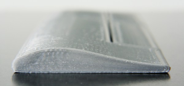
Non-planar layer Fused Deposition Modeling (FDM) is any form of fused deposition modeling where the 3D printed layers aren’t flat or of uniform thickness. For example, if you’re using mesh bed leveling on your 3D printer, you are already using non-planar layer FDM. But why stop at compensating for curved build plates? Non-planar layer FDM has more applications and there are quite a few projects out there exploring the possibilities. In this article, we are going to have a look at what the trick yields for us.
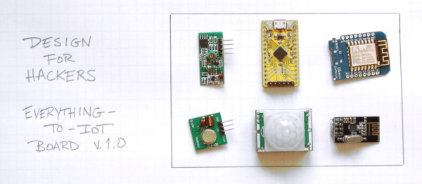
Near the end of the lifecycle of mass-market commercial product development, an engineering team may come in and make a design for manufacturability (DFM) pass. The goal is to make the device easy, cheap, and reliable to build and actually improve reliability at the same time. We hackers don’t usually take this last step, because when you’re producing just a couple of any given device, it hardly makes sense. But when you release an open-source hardware design to the world, if a lot of people re-build your widget, it might be worth it to consider DFM, or at least a hardware hacker’s version of DFM.
If you want people to make their own versions of your project, make it easy and cheap for them to do so and don’t forget to also make it hackable. This isn’t the same as industrial DFM: rather than designing for 100,000s of boards to be put together by robot assembly machines, you are designing for an audience of penny-pinching hackers, each building your project only once. But thinking about how buildable your design is will still be worthwhile.
In this article, I’m going to touch on a couple of Design for Hackers (DFH) best practices. I really want to hear your experience and desires in the comments. What would you like to see in someone else’s open designs? What drives you nuts when replicating a project? What tricks do you know to make a project easily and cheaply buildable by the average hacker?
A wild Python appeared, and it wants to play Pokemon Go. Python bots are taking over the game when you can’t, and they are good. Since you’re likely to bump into one sooner or later, here’s an overview:
One of the first workable bots and the origin of a lot of (dirty) code, as well as the (not dirty at all) Pokemon Trainer Club client secret, is [Mila432’s] Pokemon Go Bot. One of his initial goals was to make better sense of the API, which worked out better than he hoped.
Not wanting to impetuously destroy the numerous helpful applications that had been built upon the already partially known API, he decided to keep the project off Niantic’s radar. The most recent (and most powerful) version of his bot has not been released. The current version works fine within its limited functionality: Wandering around and looting Pokestops.
Since Pokemon Go blew up the world a couple of weeks ago we’ve been trying to catch ’em all. Not the Pokemon; we’ve been trying to collect all the hardware hacks, and in particular the most complete GPS spoofing hack. We are now ready to declare the first Grandmaster GPS spoofing hack for Pokemon Go. It broadcasts fake GPS signals to your phone allowing the player to “walk around” the real world using a gaming joystick.
Just about everything about this looks right to us. They’re transmitting radio signals and are doing the responsible thing by using an RF shield box that includes a GPS antenna. Hardware setup means popping the phone inside and hooking up the signal generator and GPS evaluation hardware. Google Earth then becomes the navigation interface — a joystick allows for live player movements, coordinates are converted to GPS signals which are transmitted inside of the box.
Now, we did say “just about right”. First off, that RF shielding box isn’t going to stop your fake GPS signals when you leave the lid open (done so they can get at the phone’s touchscreen). That can probably be forgiven for the prototype version, but it’s that accelerometer data that is a bigger question mark.
When we looked at the previous SDR-based RF spoofing and the Xcode GPS cheats for Pokemon Go there were a number of people leaving comments that Niantic, the devs responsible for Pokemon Go, will eventually realize you’re cheating because accelerometer data doesn’t match up to the amount of GPS movement going on. What do you think? Is this app sophisticated enough to pick up on this type of RF hacking?
The pioneering years in the history of capacitors was a time when capacitors were used primarily for gaining an early understanding of electricity, predating the discovery even of the electron. It was also a time for doing parlor demonstrations, such as having a line of people holding hands and discharging a capacitor through them. The modern era of capacitors begins in the late 1800s with the dawning of the age of the practical application of electricity, requiring reliable capacitors with specific properties.
Leyden Jars
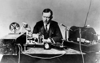
Marconi with transmitting apparatus, Published on LIFE [Public domain], via Wikimedia CommonsOne such practical use was in Marconi’s wireless spark-gap transmitters starting just before 1900 and into the first and second decade. The transmitters built up a high voltage for discharging across a spark gap and so used porcelain capacitors to withstand that voltage. High frequency was also required. These were basically Leyden jars and to get the required capacitances took a lot of space.
Mica
In 1909, William Dubilier invented smaller mica capacitors which were then used on the receiving side for the resonant circuits in wireless hardware.
Early mica capacitors were basically layers of mica and copper foils clamped together as what were called “clamped mica capacitors”. These capacitors weren’t very reliable though. Being just mica sheets pressed against metal foils, there were air gaps between the mica and foils. Those gap allowed for oxidation and corrosion, and meant that the distance between plates was subject to change, altering the capacitance.
In the 1920s silver mica capacitors were developed, ones where the mica is coated on both sides with the metal, eliminating the air gaps. With a thin metal coating instead of thicker foils, the capacitors could also be made smaller. These were very reliable. Of course we didn’t stop there. The modern era of capacitors has been marked by one breakthrough after another for a fascinating story. Let’s take a look.